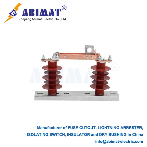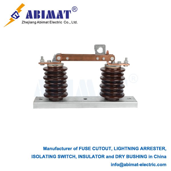
115 kV Disconnect Switch: Essential Component for Transmission System Safety & Maintenance
Operational Principle & Functional Design
In 115 kV high-voltage transmission systems, the disconnect switch (disconnector) fulfills a critical safety function distinct from circuit breakers. Although incapable of interrupting load or fault currents, its core purpose is establishing a visible air gap to safely isolate circuits, equipment, and bus sections during maintenance, commissioning, or system reconfiguration – ensuring personnel safety and operational flexibility.
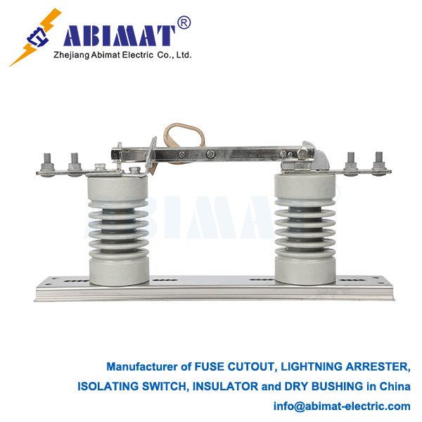
Core Functions & Operational Significance
I.Visible Air Gap Isolation:
Provides physical circuit separation verifiable at ground level. This unambiguous break is the primary safety assurance for personnel working on de-energized equipment (lines, transformers, breakers).
II.Selective Circuit Segregation:
Enables isolation of individual feeders, transformers, or bus sections without de-energizing entire substations. Critical for:
– Equipment maintenance/repair
– Power flow rerouting (contingency management)
– Pre-energization testing of new assets
III.Integrated Grounding Interface:
Often incorporates grounding blades. After main blade opening, grounding blades earth the isolated section, providing a complementary critical safety layer against accidental re-energization or induced voltages.
Design & Technical Specifications
Voltage Rating: Certified for 115 kV nominal voltage with defined dielectric withstand (BIL) and clearance margins.
Continuous Current Rating: Typically 1200A to 3000A+ at 115 kV.
Operating Mechanism:
– Gang-operated (standard): Motorized/manual ground-level drive with insulating linkages for simultaneous pole operation.
– Independent Pole Operation (IPO): Used where phase-segregated operation is justified.
Blade Architectures:
– Center-Break: Rotating blades pivot from central hinge.
– Double-Break: Horizontal/vertical motion creates two series breaks per phase.
– Vertical-Break: Gravity-assisted opening; preferred for compact substation layouts.
Auxiliary Arcing Contacts: Interrupt magnetizing/capacitive currents (e.g., transformer no-load current) without damaging main contacts.
Corona Suppression: Contoured contacts/hardware minimize RF noise and ionization at operating voltage.
Ice-Rated Operation: Meets IEC 62271-307 ice-breaking capacity requirements.
Critical Safety Protocols
Load Break Prohibition:
115 kV disconnect switches MUST NOT interrupt load current. Operation under load causes sustained arcs resulting in catastrophic equipment failure and personnel hazard. Operation permitted ONLY when:
– Upstream breaker has de-energized the circuit, OR
– Current is below arcing contact rating (verified by calculation/procedure).
Mandatory Interlocking:
Prevents:
– Operation with closed circuit breaker (load condition)
– Closing onto energized faulted circuits
– Grounding blade engagement with closed main blades
Dielectric Clearances:
Phase-to-phase/phase-to-ground clearances and insulator creepage distances comply with IEC 61936 for polluted environments.
Typical 115 kV Applications
Transformer primary/secondary isolation
Transmission line feeder isolation
Bus sectionalization (fault containment)
Circuit breaker bypass configurations
Shunt reactor/capacitor bank connections
Conclusion
The ABIMAT 115 kV disconnect switch is an indispensable asset in transmission infrastructure. Its value resides in establishing verifiable physical isolation – the foundational safety prerequisite for high-voltage work. By enabling selective de-energization and system reconfiguration, it ensures grid reliability while protecting personnel. Strict adherence to operational constraints (notably load-break prohibition) and robust interlocking are non-negotiable for safe deployment. Design evolution prioritizes enhanced environmental resilience, reduced maintenance, and integrated condition monitoring.