Author: Zhou

  • The 22 kV Pin Insulator: A Key Part of Distribution Line Insulation

    The 22 kV Pin Insulator: A Key Part of Distribution Line Insulation

    The 22 kV Pin Insulator: A Key Part of Distribution Line Insulation

    The pin insulator is a basic and strong part in electrical distribution networks. It’s mainly made to hold live conductors and insulate them from grounded utility poles. In 22 kV power systems, it’s still a cheap and reliable choice.

    Function and Design Principle

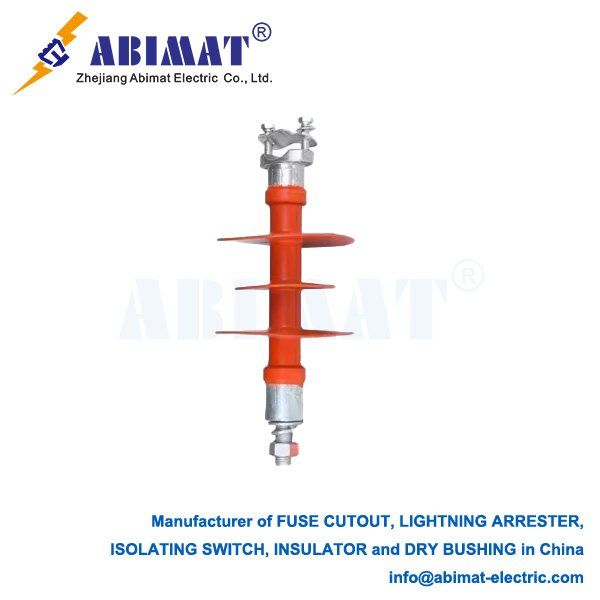
    The main job of a pin insulator is to hold the current-carrying conductor mechanically. It also electrically separates the conductor from the earthed pin it’s mounted on. Its design uses a single solid piece of insulating material. Traditionally, this material is porcelain. Now, polymer (like silicone rubber) is more common. The insulator has a series of petticoats or sheds.

    These petticoats matter a lot. They do two things. First, they make the leakage path on the insulator’s surface longer. This stops flashover when it rains, fogs or gets dirty. Second, they keep parts of the insulator dry. This makes it work better in wet conditions.

    Key Construction Features

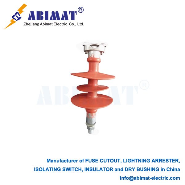
    A typical 22 kV pin insulator has several parts. It has a dielectric body. This body is either high-grade porcelain with a strong glaze or a light, water-repellent polymer housing with a fiberglass rod. It also has multiple well-designed petticoats or sheds. These sheds match the 22 kV rating and local environmental conditions. There is a groove at the top. The conductor sits here and is fixed with binding wire. At the bottom, there is a threaded cavity. It helps attach the insulator firmly to the steel pin on the cross-arm.
    Advantages and Limitations

    The pin insulator has many good points. It has a simple and durable structure with high mechanical strength. It needs little maintenance. The polymer type especially needs less because it has better water-repellent property. It’s also an economical choice for straight-line supports and low-tension uses.

    But it has some limits. It’s usually only practical for distribution voltages up to about 33 kV. For higher voltages, the insulator becomes too big and expensive. It’s also less effective when there are big horizontal loads. This happens at angles or dead-ends, where strain insulators are better.

    Material Evolution

    Porcelain has long been the traditional material. It’s very durable and has high compression strength. But composite polymer insulators are getting more popular now. They are lighter. Their water-repellent surfaces make them perform better in polluted areas. They are also more resistant to vandalism.

    Conclusion

    The abimat 22 kV pin insulator is a mature and proven technology. It still plays an important role in medium-voltage distribution. Its simple design, reliability and low cost make it a great choice for insulating overhead lines in many environments. It ensures electrical power is delivered safely and continuously.
  • The Single Break Disconnector: A Basic Safety Part in Electricity​

    The Single Break Disconnector: A Basic Safety Part in Electricity​

    The Single Break Disconnector: A Basic Safety Part in Electricity​

    For electrical power distribution and transmission, safety and reliable operation are really important. The single break disconnector—you might also hear it called a disconnect switch or isolator—is a basic piece of equipment. It’s designed for one key safety job: making a clear, safe air gap in an electrical circuit.

    Main Function and Design Idea

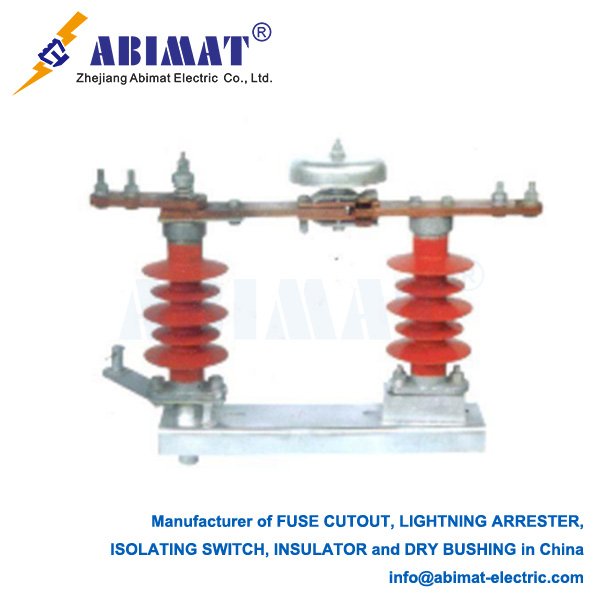
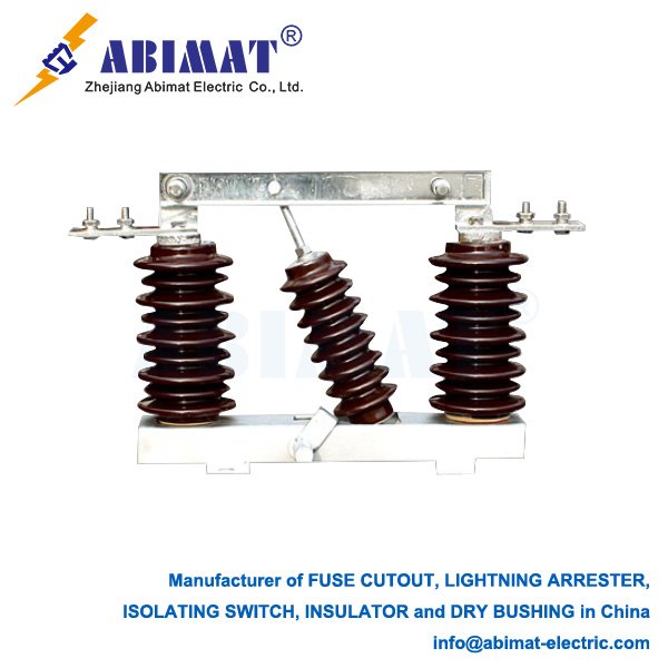
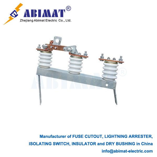
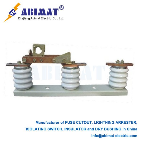
    The single break disconnector’s main job isn’t to stop load current. It’s to make sure a circuit has no power—so people can do maintenance, checks, or isolation safely. Its name comes from how it works: it makes a single, clear break in the current’s path. When the switch is open, its contacts move apart physically. This makes a visible air gap—and that gap shows you the circuit is isolated. This design is tough. It usually has a rotating blade, and this blade slides into or out of a fixed contact jaw.

    Key Operating Traits

    We need to clearly tell apart a disconnector and a circuit breaker. Disconnectors don’t have parts to stop electric arcs. So they aren’t designed to stop current when the circuit is carrying a load. You can only use them when the circuit has no power. An upstream device—like a circuit breaker—is what makes that happen. If you try to open a circuit with a load using a disconnector, it could create a dangerous, harmful arc.​
    Single break disconnectors have these main features:​
    • Visible isolation: The open gap clearly shows you how the circuit is doing.​
    • Can handle steady current well: When they’re closed, they’re built to take the full load current of the circuit—and they won’t overheat.​
    • Tough mechanical life: They’re built to work many times mechanically, and they don’t need a lot of maintenance.​
    • Can handle short-circuit currents: They have to handle short-circuit currents for a fixed time—usually one to three seconds. That’s until a protective breaker fixes the problem.

    Where They Are Used​

    Single break disconnectors are used for many different voltage levels. They’re used everywhere from medium-voltage switchgear in factories to ultra-high-voltage transmission lines. They’re put in important places to isolate transformers, circuit breakers, and busbar sections. This lets people work safely on the downstream equipment—and you don’t need to shut down the whole system.

    In short, the abimat single break disconnector is a safety device you must have for electrical systems. Its design is simple but useful—it gives the reliable isolation needed to protect workers and equipment. It’s a basic part of keeping electrical systems working safely.

  • Polymer Pin Type Insulators: A Modern Choice for Power Distribution Lines​

    Polymer Pin Type Insulators: A Modern Choice for Power Distribution Lines​

    Polymer Pin Type Insulators: A Modern Choice for Power Distribution Lines​

    Polymer pin type insulators bring big improvements to medium-voltage power distribution networks—most of these networks work up to 33 kV. They attach straight to a supporting pin on the crossarm of a utility pole. This setup keeps the live conductor from touching the grounded pole electrically.​
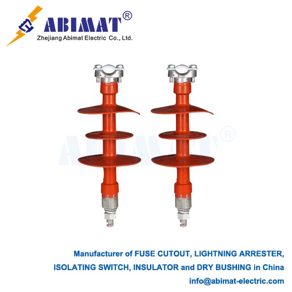
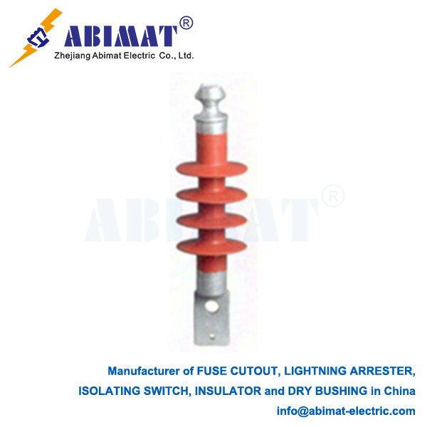
    A polymer pin insulator has three main parts: a core, a housing, and end fittings. The core is what carries the load. It’s usually made of a glass or epoxy resin rod, so it’s strong enough to handle mechanical stress. The core gets covered by a housing and sheds. These two parts use polymeric materials—silicone rubber or EPDM (ethylene propylene diene monomer) are the most common. To make these polymer housings, manufacturers use methods like injection or compression molding.​
    Polymer insulators beat traditional porcelain or glass ones in many ways. They don’t weigh much. That makes them easier to hold, move, and put in place. It also lowers labor costs and saves time. They’re also better at taking impacts. That means less chance of damage when you install them, or if someone tries to break them—porcelain insulators are brittle, so they break easily from these things.
    For how well they work electrically, the silicone rubber surface matters a lot. It pushes water away. This stops a steady film of water from forming. Less water film means less current leaking out. It also makes flashovers less likely, especially in places that are dirty or damp. The shape of the polymer sheds helps too. They clean themselves when it rains, so they still work well even in polluted areas.
    The polymer housing is flexible and stretchy too. It deals with mechanical shocks and vibrations better. The insulator is made as a single piece: the housing sticks right to the core and the metal end fittings. This makes a tight seal. It keeps moisture out—and moisture is a main reason other insulators get damaged inside.
    All in all, abimat benefit from using polymer pin type insulators. They’re more dependable, don’t need as much upkeep, and cost less over time. They’re light, work well in polluted spots, and stand up to vandalism. Because of these things, they’re the best choice for updating power distribution systems and making them more long-lasting.
  • Cut-Out Fuse Links: An Essential Component for Overhead Line Protection

    Cut-Out Fuse Links: An Essential Component for Overhead Line Protection

    Cut-Out Fuse Links: An Essential Component for Overhead Line Protection

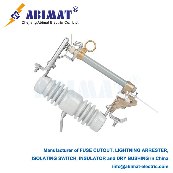
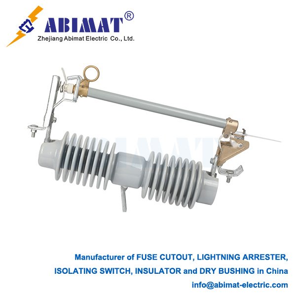
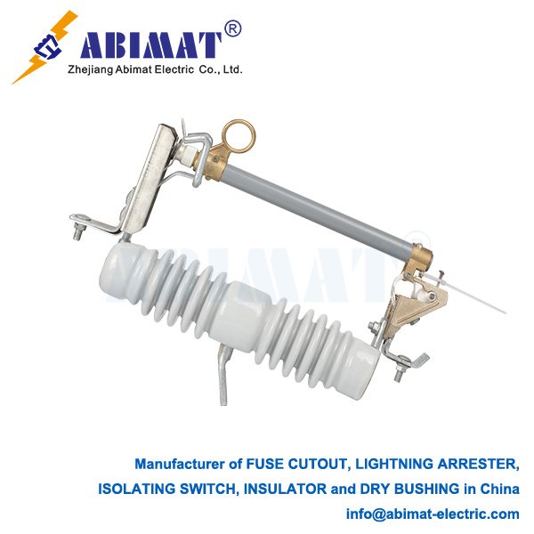
    Cut-out fuse links—people often call them drop-out fuses—are important overcurrent protection devices. We use them a lot in medium-voltage overhead distribution networks. They help isolate faulty parts cheaply and reliably, which makes the electrical supply safer and more steady.

    Construction and Key Components

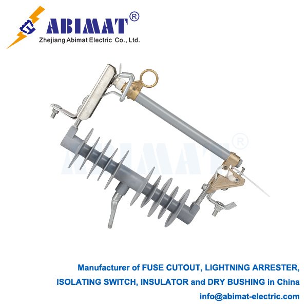
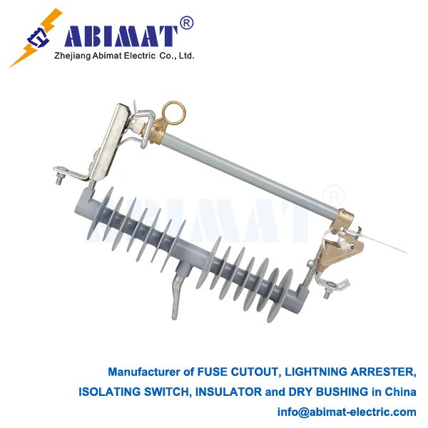
    A typical cut-out fuse setup has three main parts: a waterproof base, a fuse carrier (that’s the holder), and the fuse link itself.

    The base is made of insulating material—things like porcelain or polymer. It holds the whole setup together and has the fixed contacts inside.

    The fuse carrier is the part you can take out. It holds the fuse link, and it’s designed to pivot and “drop out” when the device works—you can see this happen clearly.

    The fuse link is a special element that’s set to work just right. It carries the load current normally, but it melts when there’s a fault.

    Operating Principle

    The device works on a simple electromechanical idea. When everything’s normal—when the load current is steady—the fuse link keeps the carrier tight in the closed position. This keeps the circuit connected.

    If there’s a short-circuit or a bad overload, the high current from that melts the fuse element fast. When this happens, an arc starts inside the carrier. Most fuse carriers have material inside to put out arcs—like boric acid or a sand-like stuff. This material makes gases that put out the arc quickly.

    At the same time, the melting fuse element does two things: it either releases a spring-loaded part or takes away the tension that held the carrier in place. Once the carrier is free, it pivots down because of gravity. It hangs open after that, and this creates a clear air break you can see. This tells you the device has worked, and it also isolates the faulty circuit.

    Primary Applications and Advantages

    We mainly use cut-out fuse links to protect three kinds of equipment:

    First, they protect distribution transformers that are mounted on top of utility poles.

    They also protect tap lines and branches of overhead feeders.

    And they protect capacitor banks and other sectionalizing points too.

    They have three big advantages:

    One, the dropped carrier shows clearly that the device has operated. This helps us find faults fast, so we don’t waste time checking.

    Two, they’re a good deal—cheap but reliable for overcurrent protection. You don’t need to spend a lot to get good performance.

    Three, they’re simple to use. They have strong parts, and not many moving pieces. So they last a long time, and you won’t struggle to operate them.

    All in all, abimat cut-out fuse links are still basic and necessary protection devices in overhead distribution systems. They balance performance, safety, and cost well—there’s no better choice for this kind of job.

  • Pole-Mounted Disconnect Switches: Essential Components for Distribution Safety and Control

    Pole-Mounted Disconnect Switches: Essential Components for Distribution Safety and Control

    Pole-Mounted Disconnect Switches: Essential Components for Distribution Safety and Control

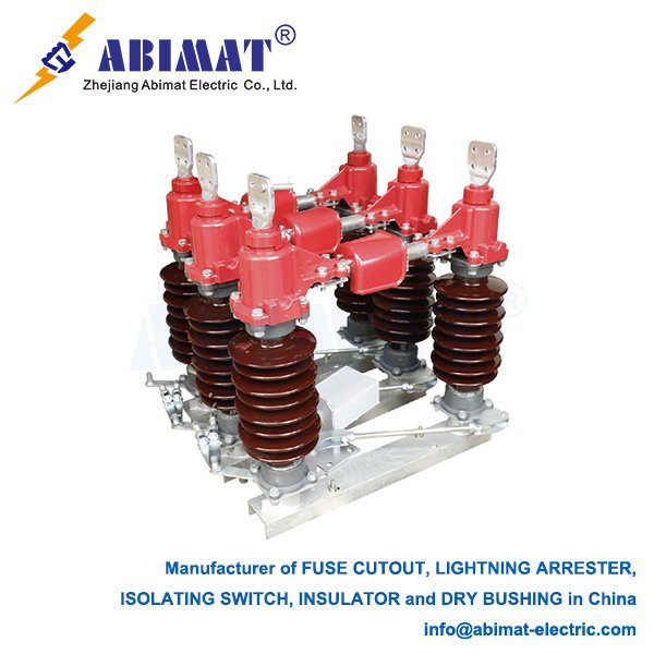
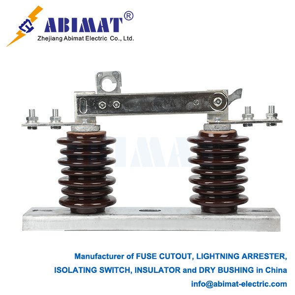
    A pole-mounted disconnect switch is a mechanical switch. We install it on power distribution poles. Its main job is to keep electrical circuits safely isolated. It does this by making a visible air gap between its contacts. This gap lets you know the circuit is separated—so you can do maintenance, fix faults, or change how the circuit works. These switches are vital—they make overhead distribution networks safer, more flexible, and more reliable.

    Core Functions and Types

    These switches work in different ways, depending on their design and what they can do.​
    One type is Disconnectors (Isolators). Their main job is safety isolation. You can only operate them when the circuit has no power—they can’t stop load current. They give a visible break, so workers can safely work on that part of the line.​
    Another type is Load Break Switches. These can turn on and off rated load currents when things are working normally. People often use them to split feeders into sections. This way, they can isolate the part of the feeder with a fault.​
    The third type is Circuit Breakers. These are more advanced protective devices. They can stop both load current and fault (short-circuit) currents. They have controllers and reclosing features. These let them automatically clear temporary faults.

    Key Design and Construction Features

    Pole-mounted switches are built to work outdoors, even in tough conditions. Here are the key parts of their design:
    First, the Insulation Medium. The insulation inside the switch is important for how it works. Common types are air insulation, oil insulation, and SF6 gas insulation. SF6 insulation is often used in imported models. It seals well and barely needs maintenance—because the inside insulation is protected from the outside environment.
    Then, the Operating Mechanism. This is the part that opens and closes the switch. It comes in different kinds. One kind is spring-operated mechanisms. These are common—you can operate them with electricity or by hand. Another kind is permanent magnet actuators. These use magnetic force to stay in place. They have few moving parts and seal well. But they might not have a manual override. That’s a problem if the power goes out.
    Last, the Construction. Most are three-pole units—they’re for three-phase systems. They’re designed to be operated by hand or with a motor.

    Critical Technical Parameters

    When you pick a switch, you need to match its ratings to the system. The essential parameters are:​
    Rated Voltage is one. It’s the highest system voltage the switch can handle normally. Examples are 12kV, 24kV, 36kV.​
    Another is Rated Current. This is the maximum current the switch can carry non-stop. Examples are 400A, 630A.​
    Next is Short-Time Withstand Current. This is the biggest fault current the switch can handle for a short time—like 4 seconds—without getting damaged.​
    Last is Power Frequency and Lightning Impulse Withstand Voltage. These are insulation tests. They check if the switch’s insulation is strong enough against temporary high voltages and lightning surges.

    Application and Selection in Distribution Networks

    Which switch you choose depends on what role it will play in the network’s automation plan.
    If you need localized automation, you use reclosers. These are circuit breakers with advanced controllers. They can automatically isolate faults and get power back on.
    For centralized control systems, using a mix of switches is usually best. You can use load break switches as cheap sectionalizing switches on the main feeder. At the same time, circuit breakers can protect branch lines. This way, you balance cost and performance.
    In summary, the abimat pole-mounted disconnect switch looks simple—but it’s really important for overhead distribution. It makes a clear, visible break in the electrical circuit. This makes it a key part of safe work practices and flexible operation. It helps keep the power grid reliable and strong.
  • 33 kV Polymer Pin Insulator: A Technical Overview

    33 kV Polymer Pin Insulator: A Technical Overview

    33 kV Polymer Pin Insulator: A Technical Overview

    ⅠIntroduction

    A Medium Voltage Disconnect (MVD) switch is a very important mechanical switching device. It’s made to safely isolate circuits in electrical power systems—usually for voltages between 1kV and 38kV. Its main job is to give a reliable, easy-to-see way to make sure a circuit is isolated. People need this for fixing, maintaining, or changing how the system works. This keeps workers safe and stops equipment from accidentally turning on.

    MVD switches aren’t like circuit breakers. They aren’t made to stop faulty currents or heavy load currents. You use them only when another protective device—like a circuit breaker upstream—has already turned off the circuit’s power. One key thing about how MVD switches are built: there’s a clear air gap between their contacts when they’re open. This gap gives a physical, sure way to know the circuit is isolated. Lockout/tagout steps depend on this important safety feature.

    Ⅱ What It’s Made Of and Key Parts

    The insulator has a strong design with several important parts:​
    One part is the Silicone Rubber Housing/Skirts. This is the outer polymer cover. It’s made from High-Temperature Vulcanized Silicone Rubber. It has good water-repelling ability—this stops water from forming a thin film on its surface. That reduces the small current that leaks out and makes it work better when there’s pollution. The skirt design also makes the “creepage distance” longer (that’s the distance electricity has to travel along the insulator’s surface). For 33kV units, this distance is usually 1330mm. It helps stop electricity from jumping over the surface (called flashover).​
    Another part is the Fiberglass Epoxy Resin Core Rod. This is the central part. It’s strong enough to hold the weight of the power conductor and handle mechanical loads. The core rod is usually very tough, with a set “breaking load” (how much force it can take before breaking).​
    The third part is the Metal Fittings. These are made from forged steel. They include parts like pins or sockets—they connect the insulator to the support structure and the power conductor. The “pin-type” design is common. It makes it easy to install on the cross-arms of power poles. You need to seal the spot where the core meets the metal well. If moisture gets in there, it can cause the insulator to break completely.

    Ⅲ Why It’s Better Than Porcelain​

    33kV polymer pin insulators have several good points for daily use:​
    One plus is better water-repelling ability. The silicone rubber surface pushes water away. Moisture forms small drops instead of a film. This reduces the small leaking current, cuts down on “dry-band arcing” (small sparks on dry spots), and lowers the chance of flashovers caused by pollution. This is especially useful in coastal areas or places with lots of industry.​
    Another plus is that it’s light and hard to damage on purpose. Polymer insulators are much lighter than porcelain ones. That makes them easier to move and install. They’re also mechanically strong and don’t shatter. So they’re hard to damage when you handle them or if someone tries to vandalize them.​
    A third plus is good performance against pollution. The water-repelling ability plus the specific shape of the skirts makes these insulators work well in places with heavy pollution, salt fog, or industrial dirt. They keep working reliably even in those conditions.

    Ⅳ Key Technical Specs​

    For a 33kV system, the insulator usually has these specs:​
    One is Rated Voltage—it’s 33 kV.​
    Another is Rated Mechanical Load—it’s 12.5 kN (that’s a unit of force).​
    Then there’s Lightning Impulse Withstand Voltage—it’s 260 kV. This is how much voltage from lightning it can handle.​
    Next is Power Frequency Wet Withstand Voltage (1 min)—it’s 130 kV. This is how much regular voltage it can handle for one minute when it’s wet.​
    Last is Nominal Creepage Distance—it’s 1330 mm.​
    These specs make sure the insulator works reliably under normal system voltage, temporary high voltages, and lightning surges.

    Ⅴ Standards and Testing​

    Polymer insulators have to follow international standards—like IEC 62217. These standards say how to test the insulators and what results count as good. Important tests are:​
    One test is Electrical Tests. These include the power frequency wet withstand voltage test and the lightning impulse withstand voltage test. They check if the insulator’s insulation is strong enough under different high-voltage conditions.​
    Another test is Mechanical Tests. These make sure the insulator can handle the specified pulling force and twisting force.​
    A third test is Material and Ageing Tests. These check things like how well the material resists tracking (small electrical paths) and erosion, if the water-repelling ability spreads to dirty parts, and how it works after being tested to simulate long-term use.

    Ⅵ Conclusion

    The abimat 33 kV polymer pin insulator is a very reliable and useful option for modern medium-voltage overhead power distribution networks. It has advantages like being light, working well against pollution, and proving to be reliable over time. That’s why power companies around the world prefer it—it helps make the power grid stronger.

  • Lightning Arresters for 11kV Lines: Essential Protection for Distribution Systems

    Lightning Arresters for 11kV Lines: Essential Protection for Distribution Systems

    Lightning Arresters for 11kV Lines: Essential Protection for Distribution Systems

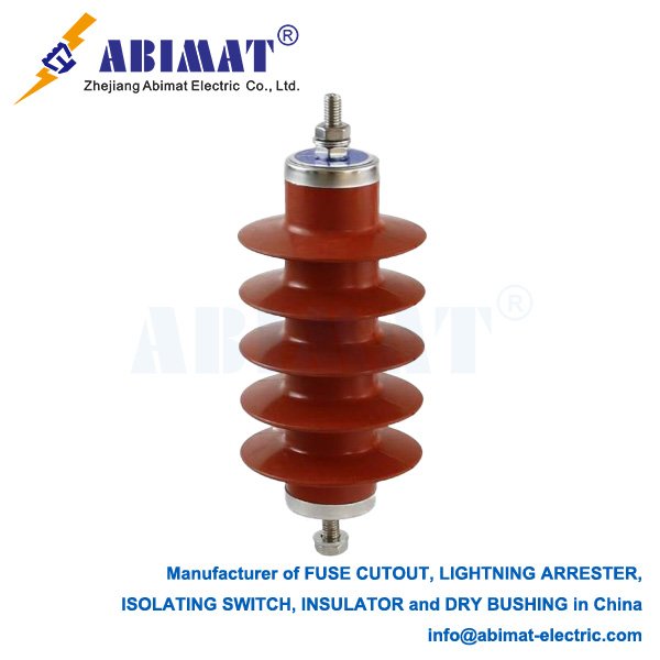
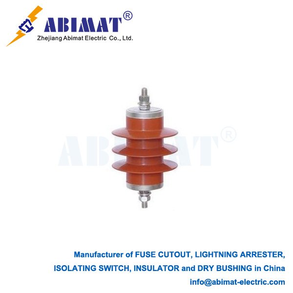
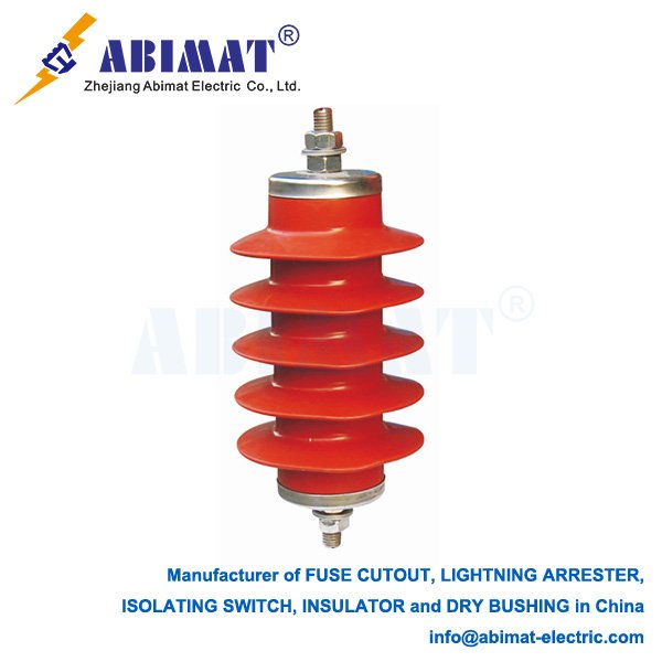
      Lightning arresters are important protective devices. They’re put on 11kV overhead distribution lines. Their job is to protect electrical equipment from harmful overvoltages—these come from lightning strikes and switching surges. The main thing they do is limit these temporary voltages to a safe level. Then they automatically get the circuit back to normal.​

    How They Work and Their Main Tech​

    Modern arresters for 11kV lines mostly use Metal-Oxide Varistor (MOV) tech. The main part is a pile of zinc oxide discs. These discs have a very non-linear voltage-current trait. When the system voltage is normal—like 11kV—the MOV has very high resistance. Only a tiny bit of leakage current can get through.​
    But if there’s an overvoltage from lightning (it can reach hundreds of kilovolts), the MOV’s resistance drops almost right away. This makes a low-resistance path to the ground. The surge current goes through this path, and the arrester limits the voltage across the equipment to a safe value. People call this value “residual voltage” or “impulse residual voltage.” Once the surge is gone, the arrester goes back to having high resistance.

    Key Types: Gapped vs. Gapless​

    There are two main types, and they’re different because of their structure.​
    One is Gapless Arresters (NGLA). These are the most common type now. The MOV blocks connect directly between the line and the ground. They work well, react fast, and people usually use them to protect important equipment.​
    The other is Arresters with External Series Gap (EGLA). This kind has a metal-oxide part connected in a line with an outside air gap. The gap keeps the MOV away from the system voltage when things are normal. This stops leakage current and slows down aging. When there’s an overvoltage, the gap creates a spark. This lets the MOV limit the surge. EGLAs are often a good choice for general line protection—they’re strong and last a long time.

    Important Technical Things for 11kV Systems​

    When you pick an arrester, you need to match its ratings to the 11kV system. Key things to look at are:​
    One is Rated Voltage. This is the highest voltage the arrester can handle when it’s working. For an 11kV system, this is usually 12.7kV or 17kV.​
    Another is Residual Voltage (Impulse). This is the voltage you measure across the arrester when it lets out a certain surge current. For example, an arrester rated 17/50kV has a residual voltage of 50kV for a standard 8/20 µs current wave.​
    Then there’s Continuous Operating Voltage. This is the highest RMS voltage that can be applied to the arrester non-stop. For an 11kV line, this is usually 10.4kV to 13.6kV.​
    The last one is Nominal Discharge Current. This is the peak value of the lightning current impulse—usually an 8/20 µs waveform. People use this to sort the arrester. For distribution lines, 5kA or 10kA is common.

    Using Them and Things to Think About When Picking​

    Picking the right one is important for it to work reliably. In places where there’s a lot of lightning, you should use arresters that can let out more current—like 10kA.
    Choosing between EGLA and NGLA means thinking about a few things: how much they cost, how well you need them to protect, and how easy they are to maintain.
    You need to check them regularly. For gapless ones, it’s a good idea to check the leakage current every year before thunderstorm season. For gapped ones, you should check the gap distance every two years.
    To sum up, using abimat lightning arresters the right way is a basic and cheap way to make 11kV distribution networks more reliable and last longer. They stop lightning from causing damage, so the power supply stays stable.
  • Expulsion Fuses: A Fundamental Protective Device in Electrical Distribution

    Expulsion Fuses: A Fundamental Protective Device in Electrical Distribution

    Expulsion Fuses: A Fundamental Protective Device in Electrical Distribution

      An expulsion fuse is a common device that protects against too much current. It’s used in medium-voltage electrical distribution systems—usually between 2.4 kV and 38 kV. Its main job is to stop fault currents safely. It does this by pushing out the arc plasma made when the fuse melts, and that’s where its name comes from. It’s a cheap and reliable way to protect transformers, capacitors, and parts of feeder lines.​

    How It Works​

      The main part of an expulsion fuse is a fusible element—it’s often a tin or silver wire. This element is inside a strong tube. The tube is made of a material that stops arcs, like fiberglass or boric acid. When things work normally, the fusible element carries the load current without stopping. If there’s too much current that won’t stop, or a short-circuit fault, the element gets hot and melts fast—that’s what “fuses” means here.​
      The fault current makes intense heat. This heat turns the metal into vapor, and that starts an electric arc. At the same time, the inside lining of the fuse tube breaks down because of the extreme heat. This makes a lot of deionizing gas. This gas has high pressure. It builds up inside the tube and gets pushed out hard from one end—or both ends. This stretches the arc and cools it down. It keeps cooling until the arc goes out when the current hits a natural zero. The whole process of stopping the current usually happens in half a cycle of the AC power frequency.

    Key Parts and Traits​

      First, the fuse tube. It’s a hollow insulator that holds the fusible element. It also handles the system voltage. The inside lining of the tube is important—it helps stop arcs well.​
    Then the fusible element. It’s set exactly to melt at a certain current and time. This lets it work well with other protective devices—you can predict how it’ll act, and it picks the right time to work.​
    Third, the end fittings. They give points to connect electricity. They also usually hold the hardware for mounting.​
      Many expulsion fuses have a key feature—it’s called the “drop-out” action. After the fuse works, the fuse tube (or a visible indicator) comes loose and falls down. This gives a clear, easy-to-see sign that the fuse has worked. It helps linemen find the broken section fast.

    Good Points and Limits​

      People like expulsion fuses for a few reasons. They’re simple, they last long, and for their size and cost, they can stop a lot of current. Another safety plus? After they work, you can see a clear open gap.​
      But they do have limits. When they work, they can make a loud noise and let out hot gases. So you need enough space around them. They aren’t good for fully closed indoor equipment. They also aren’t good if you need something that limits current. What’s more, the temperature around them and how you install them can change how they work a little.​
      To sum up, abimat expulsion fuses are still a key part of protecting distribution systems. They work well, show when they’ve operated, and don’t cost too much. This design keeps them useful—they help protect electrical infrastructure from the damage that too much current can cause.
  • Medium Voltage Disconnect Switch: A Vital Component for Electrical Safety

    Medium Voltage Disconnect Switch: A Vital Component for Electrical Safety

    Medium Voltage Disconnect Switch: A Vital Component for Electrical Safety

    A Medium Voltage Disconnect (MVD) switch is a very important mechanical switching device. It’s made to safely isolate circuits in electrical power systems—usually for voltages between 1kV and 38kV. Its main job is to give a reliable, easy-to-see way to make sure a circuit is isolated. People need this for fixing, maintaining, or changing how the system works. This keeps workers safe and stops equipment from accidentally turning on.

    MVD switches aren’t like circuit breakers. They aren’t made to stop faulty currents or heavy load currents. You use them only when another protective device—like a circuit breaker upstream—has already turned off the circuit’s power. One key thing about how MVD switches are built: there’s a clear air gap between their contacts when they’re open. This gap gives a physical, sure way to know the circuit is isolated. Lockout/tagout steps depend on this important safety feature.

    MVD switches are built strong. They can handle tough environmental conditions and electrical needs. They also usually have insulated rods for operating. These rods let people switch them safely from far away. To stop unsafe use, MVD switches often have interlocks. These are mechanical or electrical systems. They keep the switch from opening when there’s a load on it, or closing when that’s unsafe. This helps lower the risk of arc flashes and damage to equipment.

    MVD switches are used in many places—both for utilities and in industry. You can find them in electrical substations. They’re also at the power supply points for big factories, mines, and large commercial buildings. Plus, they’re in distribution networks. There, they isolate certain parts. This is for handling faults or controlling loads.

    All in all, abimat MVD switches are safety devices you can’t do without. They give a clear gap and a reliable way to isolate circuits. This makes them a key part of safe work habits. They help make sure people can maintain and run electrical systems without danger.

  • Overhead Disconnect Switches: A Critical Component in Electrical Power Systems

    Overhead Disconnect Switches: A Critical Component in Electrical Power Systems

    Overhead Disconnect Switches: A Critical Component in Electrical Power Systems

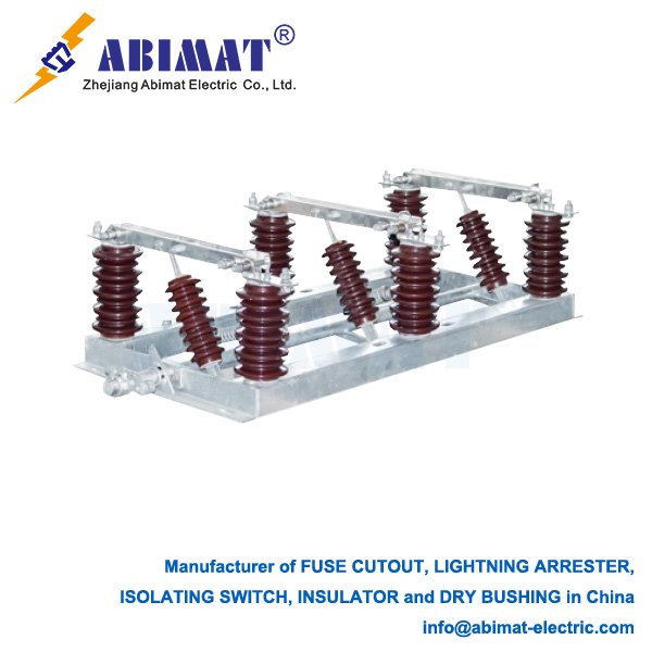
      An overhead disconnect switch, which people also call an air-break switch or isolation switch, is a basic mechanical switching tool. It’s used in high-voltage electrical power systems. Its main job isn’t stopping load current—instead, it gives a safe, easy-to-see way to separate a part of a circuit. This helps with maintenance, repairs, or changing where power goes. You’ll see these switches everywhere—in substations and along power lines—and they’re a key part of keeping the system safe, flexible, and reliable.
    ​
      It has one key thing about it: you can only use it when the circuit it controls has no power. It doesn’t have the parts that stop arcs—those are the parts circuit breakers have. Circuit breakers are built to safely stop fault currents and load currents. When an overhead disconnect switch opens, it creates a visible “air gap” between its contacts. This physical gap is a clear open spot you can check, and it’s really important for workers who fix equipment downstream. You usually operate it by hand, either with a turning handle or a push-pull stick on the ground. Sometimes you can operate it from a distance too, using a motor-driven part.
    ​
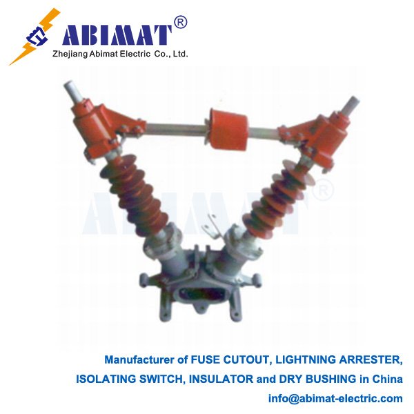
      Overhead disconnect switches are built to work well outdoors, even in tough conditions. Their parts usually include three main pieces. One is blades and contacts. The moving blade—usually a flat or tube-shaped conductor—turns to connect to the fixed jaw or disconnect from it. The contacts are made to press together tightly, and this keeps electrical resistance low. It also handles fault currents.
      Another piece is insulators. Porcelain or polymer insulators hold the parts that carry current. They also keep those parts insulated from the grounded support structure. The third piece is the operating part. It’s a strong mechanical part that connects things. It takes your input—either manual or motor-driven—and turns it into the blade’s turning movement.
      Common types are single-side-break, double-side-break, and center-break (or vertical-break) switches. The center-break type has two moving blades, and these blades open up and down. It’s better at making a good air gap, and it also works better to stop small capacitive currents—like the ones from power lines that aren’t carrying a load.
     
      They’re mainly used to isolate equipment—things like transformers, capacitor banks, or whole feeder lines. This lets workers do maintenance safely, without cutting power to a bigger part of the grid. They also work with circuit breakers in a “series-isolation” setup. You open the circuit breaker first. This cuts power and stops any current. After that, you open the disconnect switch—that gives the visible separation.
     
      To sum up, an abimat overhead disconnect switch looks simple, but it’s really important. It creates a clear, easy-to-see break in an electrical circuit. It’s the foundation of safe work practices, and it also helps keep modern power systems flexible to run.