Author: Zhou

  • The 20 kV Lightning Arrester: Essential Protection for Medium-Voltage Systems

    The 20 kV Lightning Arrester: Essential Protection for Medium-Voltage Systems

    The 20 kV Lightning Arrester: Essential Protection for Medium-Voltage Systems

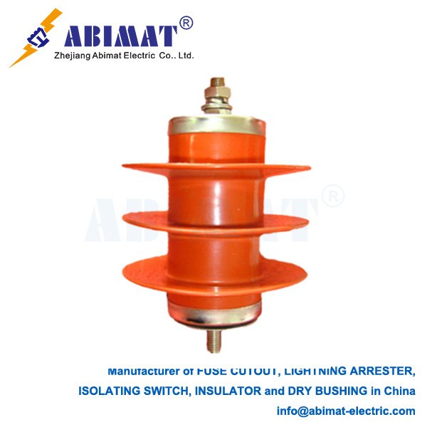
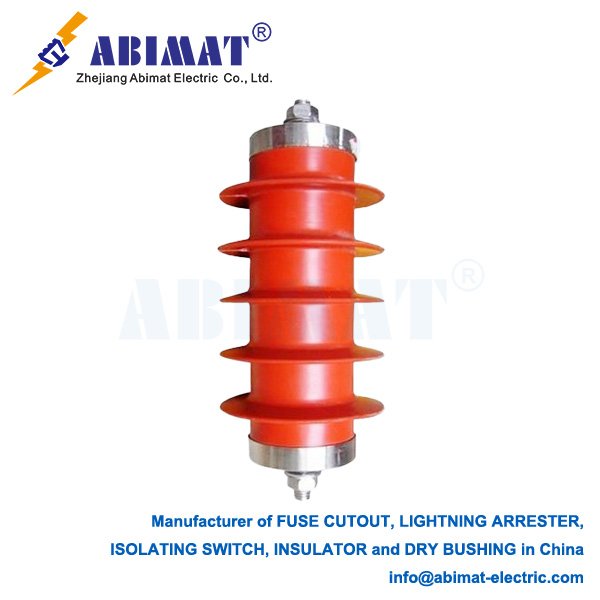
    A 20 kV lightning arrester—people often call it a surge arrester too—is a key protective device. It gets installed in medium-voltage (MV) electrical networks. These networks usually range from 12 kV to 24 kV. Its main job is to protect expensive equipment. Things like transformers, switchgear and cables are the ones it safeguards. It does this by limiting sudden overvoltages. Most of these overvoltages come from lightning strikes or switching operations.

    Under normal working conditions, the arrester has very high impedance. This means it basically acts like an open circuit. It keeps itself separate from the live system because of this. The core part of the arrester is a stack of Metal-Oxide Varistor (MOV) discs. These discs are mostly made of zinc oxide (ZnO). They also have other metal oxide additives.

    ZnO varistors have a very non-linear voltage-current feature. A transient overvoltage can happen sometimes. If that overvoltage goes above the system’s protective level, the arrester’s impedance drops a lot. This creates a low-impedance path to the ground. The surge current can then flow safely through this path. It gets diverted and turns into heat, which fades away. Once the transient is gone, the system voltage goes back to normal. Then the arrester quickly gets its high impedance back. This lets it isolate again, and it doesn’t stop the power flow.

    Choosing the right arrester for a 20 kV system needs looking at several key things. First is the Rated Voltage (Ur). This is the highest power-frequency voltage the arrester can handle. It has to do this after it diverts a surge, usually for 10 seconds. A 20 kV system has a nominal voltage around 20-22 kV. For this kind of system, a common Ur is 24 kV or 27 kV. People pick these to handle temporary overvoltages (TOVs).
    Next is the Nominal Discharge Current (In). This is a standard current wave. It’s used to sort the arrester’s duty cycle. For distribution-class arresters, 5 kA or 10 kA is typical for this current.

    Then there’s Residual Voltage (Ures). This is the voltage across the arrester’s terminals. It shows up when the arrester discharges the nominal current. This parameter is key—it defines the protective level. A lower residual voltage means better protection for the connected equipment.

    Line Discharge Class is another one. It sorts how much energy the arrester can take for switching surges.

    20 kV surge arresters get put in important spots in the network. One spot is on overhead line poles. They protect distribution transformers there. Another is at the entrance of substations. They shield switchgear and cables there. They also go at the terminals of rotating machines. Things like motors or generators are these machines.

    These arresters clamp down on transient overvoltages reliably. This stops insulation breakdown. Insulation breakdown is the top reason equipment fails from surges. Doing this makes the system more reliable. It cuts maintenance costs. It also makes critical assets last longer.

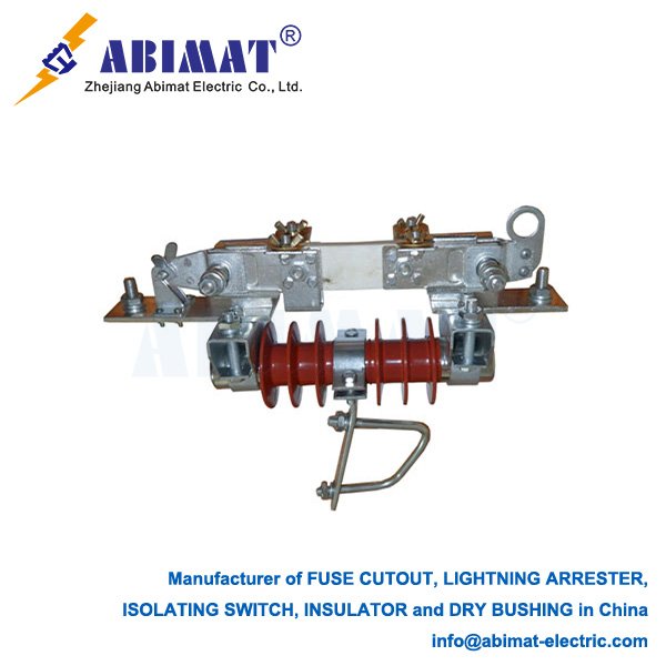
    The abimat 20 kV metal-oxide surge arrester is a smart and necessary guardian. It looks after medium-voltage power systems. It has fast-acting, non-linear features. These features give strong defense against the harmful energy from lightning and switching surges. This makes sure the electrical supply stays stable and keeps running. Picking the right arrester and using it correctly is very important. It helps make a protection plan that works well and is strong.
  • The Critical Role of the Drop Out Fuse Cutout Cover

    The Critical Role of the Drop Out Fuse Cutout Cover

    The Critical Role of the Drop Out Fuse Cutout Cover

    The drop out fuse cutout is a basic overcurrent protection device. It’s widely used in electrical distribution networks, especially on overhead lines. The fuse element inside is the main part that provides protection. But the external cover—people often call it a fuse cover, arc hood, or bird guard—also plays a key role. It has many functions that help keep the device running safely and reliably.

    Primary Functions and Design

    The cover is usually made from strong, weather-resistant polymer materials. These materials can handle long-term UV exposure, very high or low temperatures, and mechanical impacts. The cover isn’t just a protective shell. Its design is made to serve specific important functions.

    First, it contains arcs and gases. When the device stops a fault, the internal fuse element melts. This creates a high-energy electric arc. The strong cover holds this arc and the hot gases that come with it. It stops them from spreading into the surrounding area. This is important because it prevents phase-to-phase faults and wildfires. It also keeps nearby workers safe.

    Another function is to stop animals from getting in. Wildlife—like squirrels and birds—often causes power outages on overhead systems. They touch live parts by accident. The fuse cover acts as a physical barrier. It stops animals from connecting the energized upper contact and the grounded mounting bracket. This helps keep the power supply running more steadily.

    The cover also protects the device from the environment. It shields the internal fuse holder and fuse link from direct rain, snow, dust, and dirt. This protection matters because it stops conductive films from building up on insulator surfaces. If those films form, they can cause tracking, flashover, and make the fuse work when it shouldn’t.

    Many modern covers have colored flags or indicators. When the fuse works and the fuse holder drops open, this mechanism shows a clear sign from the ground. Utility crews can use this sign to find and isolate the faulty section quickly. This makes their work easier and faster.

    Conclusion

    To sum up, the abimat drop out fuse cutout cover is more than just an extra part. It’s a critical component for safety and reliability. It makes sure the fuse works as it should in all environmental conditions. It contains internal faults, stops external faults caused by animals, and shows clear signs of how the device is working. For these reasons, the fuse cover is essential for keeping the electrical distribution system whole and strong.

  • The Load Break Disconnect Switch: Purpose and Operation

    The Load Break Disconnect Switch: Purpose and Operation

    The Load Break Disconnect Switch: Purpose and Operation

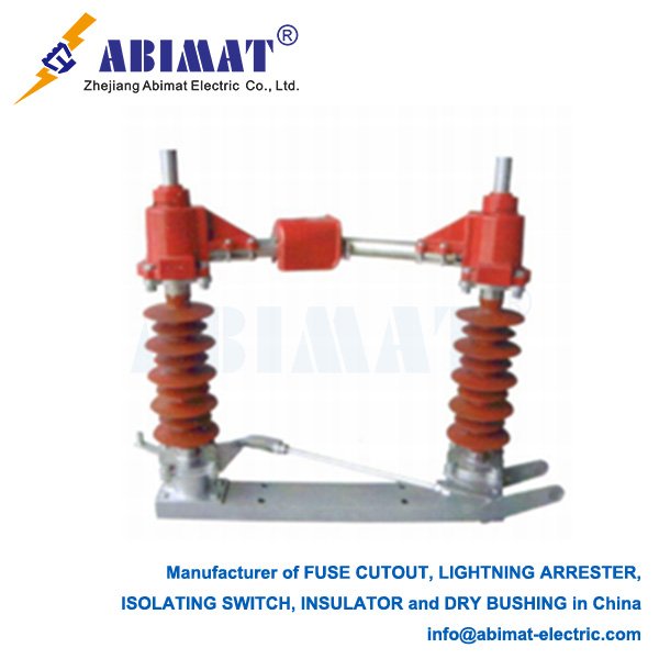
    A Load Break Disconnect Switch (LBDS) is a critical component in medium-voltage electrical distribution systems. It has a clear and vital function:to safely cut off and establish load current under normal operating conditions. This feature makes it different from a simple isolator. An isolator is only meant to open a circuit after another device has de-energized it,and it provides a visible air gap for safety.​

    Key Function: Making and Breaking Load Current​

    The main purpose of an LBDS is to perform switching operations on energized circuits. It handles tasks like these:​
    • Isolating a section of a feeder for maintenance work.​
    • Transferring load from one source to another.​
    • Switching off transformers or capacitor banks when they are under load.​
    To do these tasks safely,the switch is equipped with specialized arc-interruption technology. But we need to note that,unlike circuit breakers which can cut off high-magnitude short-circuit faults,an LBDS is only designed for rated load currents and minor overloads.

    Arc Interruption Mechanism​

    The switch’s ability to break load current comes from its engineered arc control. A common and effective design uses arcing horns or contacts with spring-assisted,quick-make/quick-break mechanisms. When the operator opens the switch,the main contacts separate first. This action transfers the current to the arcing contacts. As these arcing contacts separate,an electric arc is formed.​
    The switch is designed to stretch and cool this arc quickly. For air-insulated switches,electromagnetic forces and thermal buoyancy drive the arc upwards. Often,the arc is pushed into arc chutes made of deionizing plates. These plates split the arc into smaller segments,cool it down,and make sure it is extinguished when the current crosses zero for the first time. In other designs,a puff of air or gas may be used to help put out the arc.

    Safety and Interlocking​

    Safety is the top priority here. Load break switches are usually operated manually with an insulated pole from ground level. They are often integrated with strong mechanical interlocks. These interlocks prevent the switch from operating when the associated circuit breaker is closed. This ensures the switch never opens under a fault condition that it is not rated to handle.
    The abimat Load Break Disconnect Switch is a purpose-built device. It offers both the safety of visible isolation and the operational flexibility of on-load switching. Its specialized arc-interruption capability makes it an indispensable device. It helps manage and isolate sections of a live electrical network safely and efficiently.
  • Isolator Polymer: A Technical Overview

    Isolator Polymer: A Technical Overview

    Load Break Disconnects: Purpose and Operation

      Isolator polymers—people also call them polymeric insulating materials or insulating polymeric materials—are special polymers. They’re made to give electrical insulation and mechanical support. They’re used in high-voltage jobs, like power transmission and distribution systems. These materials usually have a composite structure. Often, they use silicone rubber or ethylene propylene diene monomer (EPDM). They mix these with a fiberglass or epoxy resin core.  

    Key Characteristics

      They have high dielectric strength. That means they work really well as insulators. They can handle strong electric fields without breaking down. Their volume resistivity is usually over 10⁹ Ω·cm. This makes them perfect for keeping live wires away from grounded parts.  

      They’re lightweight and tough. Compare them to old-style porcelain or glass insulators—these polymer ones are lighter. They’re easier to carry, and they don’t break easily if something hits them.  

    They have hydrophobicity, especially the ones made with silicone rubber. That means they repel water. This helps cut down on leakage currents. It also lowers the risk of flashover in places that are polluted or humid.  

      They can stand up to UV rays, extreme temperatures, and chemical exposure. Engineers make these materials to do this. This makes sure they stay stable and work well for a long time.  

    Applications

      People use polymer isolators in many places. First, high-voltage transmission lines—they work as disc insulators or post insulators here. They support the wires and keep them electrically separate. Then, substations—they insulate busbars and equipment there. Also, electronic devices—they act as encapsulation materials for semiconductors. This protects the semiconductors from moisture and dirt.  

    Advantages Over Traditional Materials

      They’re better than traditional materials in some key ways. They work better in harsh conditions. Their hydrophobic surface stops water from forming a film on them. This makes them more reliable in wet or dirty places. They’re also easier to install. They weigh less, so moving them and putting them together is simpler. They last a long time too. They don’t corrode easily, and they don’t age fast. This means they can work reliably for decades.  

    Future Developments

      Scientists and engineers are doing research on them. They want to make the materials better. One focus is higher thermal stability—like getting H/C-class insulation ratings. Another is making them more resistant to UV rays. They’re also working on sustainable versions. These versions use recycled polymers.  

      All in all, isolator polymers are a big step forward in electrical insulation technology. They have a good mix of reliability, durability, and efficiency. These things are important for modern power systems.

  • The Drop-Out Fuse: A Vital Protective Device in Distribution Networks

    The Drop-Out Fuse: A Vital Protective Device in Distribution Networks

    The Drop-Out Fuse: A Vital Protective Device in Distribution Networks

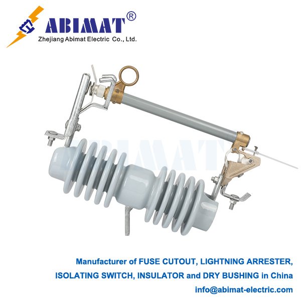
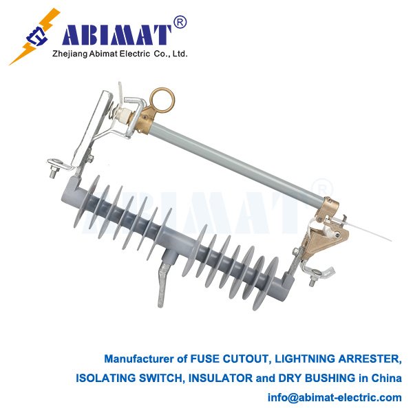
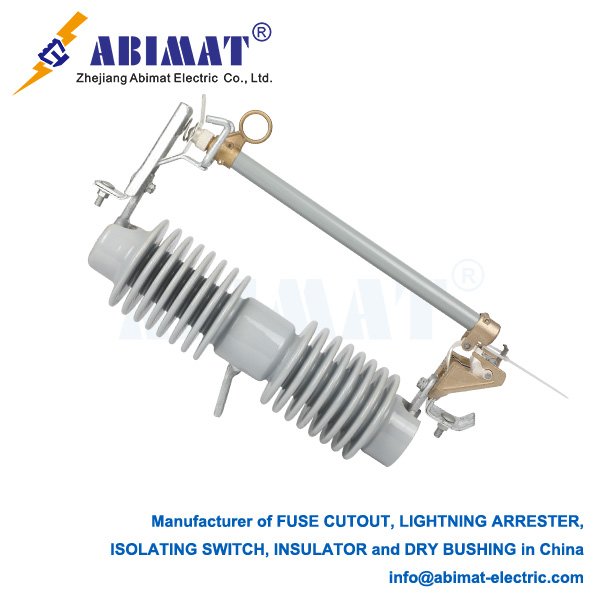
    A drop-out fuse—sometimes called an expulsion-type fuse—is a key device that protects against too much current. It’s used a lot in overhead medium-voltage distribution systems—usually 11 kV to 33 kV. It does two main jobs: it stops fault currents reliably, and it shows clearly when it’s worked. This helps isolate the broken parts of the network, like distribution transformers or feeder branches.​

    Parts of the Device​

    The device has three key parts.​
    The first part is the base. It’s a strong insulating structure fixed to the crossarm. It has upper and lower contact terminals.​
    The second part is the fuse holder—sometimes called a tube. It’s a hollow tube, usually made of fiberglass or phenolic resin. It’s made to hold the fuse link. The inside of the tube is designed to make and let out gases that stop arcs.​
    The third part is the fuse link. It’s a part you can replace. It’s set exactly to melt at a certain current and time. It carries the normal load current.

    How It Works​

    When the load is normal, the fuse holder stays closed and up. The mechanical tension of the fuse link holds it that way. This creates a continuous path for current through the device.​
    If there’s too much current for a long time, the fuse link gets hot and melts. This stops the circuit. The electric arc that forms inside the tube breaks down the lining material fast. This makes a lot of gas. The gas is pushed out lengthwise. This creates a blast. The blast stretches the arc, cools it down, and stops it from burning.​
    When the fuse link melts, it lets go of the tension that holds the tube. Then the holder can move freely on its lower hinge. Gravity pulls it down, so it swings downward. This “drop-out” action makes a clear, sure air gap. It tells people the fuse has worked, and it isolates the circuit downstream. This clear visual sign is a very important safety feature for line crews.

    Good Points and Uses​

    People like drop-out fuses for these reasons:​
    They show when there’s a fault clearly—the dropped position lets everyone know if it’s worked.​
    They’re good for saving money. They work well and don’t cost much to protect against too much current.​
    They can isolate circuits too—the air gap acts as a physical barrier for safe maintenance.​
    They’re simple. Their strong mechanical design means they last a long time, and you don’t need to fix them much.​
    They’re mainly used to protect transformers mounted on poles, capacitors, and to divide overhead lines into sections.

    Conclusion​

    The abimat drop-out fuse is still a key part of protecting overhead distribution systems. It combines two useful things well: it stops arcs reliably, and it gives clear visual signs. This makes it a device you can’t do without—it helps make the system more reliable and safer. To make it work well, you need to choose the right one, match it with the protection upstream, and check and fix it regularly.
  • Polymer Dead-End Insulators: Modern Strength for Distribution Lines

    Polymer Dead-End Insulators: Modern Strength for Distribution Lines

    Load Break Disconnects: Purposeful Switching in Medium-Voltage Systems

    A Load Break Disconnect (LBD) is an important piece of equipment in electrical distribution systems. It’s built to safely make and break load currents when the system is working normally. It has a clear job—filling the gap between what a simple isolator (disconnector) does and what a full-rated circuit breaker does

    The main job of an LBD is to give a safe, easy-to-see way to isolate a circuit with no power. It can also stop rated load currents. This makes it different from two other devices:

      An Isolator (Disconnector): This device is made to open a circuit only after something upstream (like a circuit breaker) stops the current. It gives a safe, easy-to-see air gap for maintenance work. But it can’t stop current itself.

      A Circuit Breaker: This device can stop normal load currents. It can also safely stop large short-circuit (fault) currents.

    An LBD doesn’t have the complicated parts that stop fault arcs. So it must always be used with upstream fuses or circuit breakers. These parts protect the system from faults.

    When the contacts inside an LBD move apart while carrying load, an electric arc forms naturally. The LBD is built with special parts to put out this arc safely. This arc is usually held inside a sealed space. The space is filled with a dielectric material—like oil, air, or SF6 gas (which is most common in new designs).

    The parts that control the arc (they usually use pistons or blowers) stretch the arc, cool it down, and remove its electric charge. They do this until the arc can’t keep going anymore. Then the current is stopped successfully. This lets workers safely turn off power to transformers, capacitors, cables, and other medium-voltage equipment. They do this during planned maintenance or when they need to reconfigure the system.

    LBDs have three key features:

      Rated Voltage – this is the voltage they’re made for (like 15 kV or 25 kV)

      Rated Continuous Current – this is the current they can carry nonstop

      Rated Load Break Current – this is the exact current level they’re approved to stop

      People use LBDs in a few common ways:

      They isolate transformers or capacitor banks from the live electrical network

      They split overhead distribution lines into sections. This helps isolate parts that have faults

      They work as the switching part in pad-mounted switchgear and ring main units

    The abimat Load Break Disconnect is a special, low-cost way to handle normal switching work in medium-voltage networks. Engineers need to understand what it can do and what it can’t. One important thing: it’s not made to stop faults. If they know this, they can use LBDs well. This makes the network more flexible to operate and safer.

  • Primary Uses of the Drop-Out Fuse in Electrical Distribution Systems

    Primary Uses of the Drop-Out Fuse in Electrical Distribution Systems

    Primary Uses of the Drop-Out Fuse in Electrical Distribution Systems

    The drop-out fuse—people also call it an expulsion-type fuse cutout—is a key part in medium-voltage overhead distribution networks. These networks usually range from 11kV to 33kV. Its design smartly combines two functions: overcurrent protection and a disconnecting switch you can see. So it’s a must for utility companies. Its main uses focus on keeping equipment safe and making sure operations stay safe.

    The drop-out fuse—people also call it an expulsion-type fuse cutout—is a key part in medium-voltage overhead distribution networks. These networks usually range from 11kV to 33kV. Its design smartly combines two functions: overcurrent protection and a disconnecting switch you can see. So it’s a must for utility companies. Its main uses focus on keeping equipment safe and making sure operations stay safe.

    Another important use is to protect feeders and split circuits. Workers put fuses in smart spots along distribution feeders. This lets them isolate specific sections that have faults. People call this practice segmentation. It means fewer customers lose power during an outage. For example, if a fault happens downstream, only the fuse closest to the fault works. It shuts off the problem area. The upstream parts of the line stay energized. This makes the power supply more reliable overall. It also keeps service going longer.

    Another important use is to protect feeders and split circuits. Workers put fuses in smart spots along distribution feeders. This lets them isolate specific sections that have faults. People call this practice segmentation. It means fewer customers lose power during an outage. For example, if a fault happens downstream, only the fuse closest to the fault works. It shuts off the problem area. The upstream parts of the line stay energized. This makes the power supply more reliable overall. It also keeps service going longer.

    To sum up, the abimat drop-out fuse is mainly used for three things: protecting transformers, splitting feeder sections, and protecting capacitor banks. It can provide reliable overcurrent protection. It also creates a clear break you can see. These two things together make it a key part of safe and efficient overhead electrical distribution systems.

  • 20 kV Lightning Arresters: Essential Protection for Medium-Voltage Systems

    20 kV Lightning Arresters: Essential Protection for Medium-Voltage Systems

    20 kV Lightning Arresters: Essential Protection for Medium-Voltage Systems

      A 20 kV lightning arrester—most people call it a surge arrester, and that’s more accurate—is a key device that protects electrical power systems. It mainly keeps safe the equipment that works at medium-voltage levels.

      Its main job is to protect transformers, switchgear and other expensive equipment. These pieces of equipment can get damaged by sudden high voltages. Most of the time, these high voltages come when lightning hits power lines—or hits near them. Sometimes, they also come from switching work in the power network.

    Operating Principle

    During normal use, the voltage of the 20 kV system is much lower than the arrester’s trigger point. When that happens, the arrester has very high resistance. It acts almost like an open circuit, so the power system works normally without any problems.

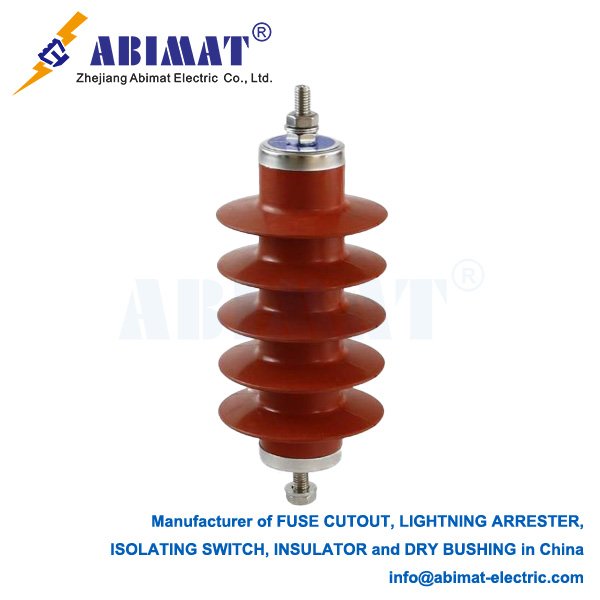
    The core of a modern 20 kV arrester is a set of Metal-Oxide Varistor (MOV) discs. Most of these discs are made from zinc oxide. They have a special trait—their relationship between voltage and current isn’t linear at all.

    If a sudden high voltage—like a lightning surge—makes the voltage at the arrester’s ends hit a certain level (people call this level sparkover voltage), the resistance of the MOV material drops a lot. After that, the arrester becomes very conductive. It gives the strong surge current an easy path to the ground.

    This way, the arrester sends the dangerous surge energy to the ground safely. It also keeps the voltage across the protected equipment at a safe level—people call this level residual voltage.

    When the surge is gone and the system’s voltage goes back to normal, the MOV discs automatically get high resistance again. That cuts off the ground connection. So the power system can start working normally again.

    Key Components and Selection Criteria

    A regular 20 kV arrester has several parts:

      MOV Block: This is the main part made of zinc oxide. It soaks up the surge energy.

      Housing: It’s made of porcelain or polymer. It gives the arrester strength, protects it from the environment, and stops electricity from leaking.

      Sealing System: It stops water from getting inside. This is very important—if the arrester is going to work well for a long time.

      End Fittings: They let the arrester connect tightly to the power line and the ground.

    When engineers choose a 20 kV arrester, they need to think about several important things:

      Rated Voltage: This is the highest regular power voltage the arrester can handle without stopping.

      Duty Cycle: This tells how well the arrester can handle sudden high voltages that don’t last long.

      Nominal Discharge Current: This is the highest point of the lightning current—people use it to sort the arrester (like 5 kA or 10 kA).

      Line Discharge Class: This shows how much energy the arrester can handle from switching surges.

      Residual Voltage: This is the voltage you measure across the arrester when it releases the nominal current. A lower number here means the arrester does a better job of protecting.

    Conclusion

    The abimat 20 kV lightning arrester is a must-have for medium-voltage power networks. It helps these networks work reliably and last for a longer time. The arrester works well to stop sudden high voltages. This keeps equipment from breaking, cuts down on power outages, and makes sure electricity is delivered safely without stopping. To let these devices do their important protective job well, you need to choose the right one, install it the right way, and check it on a regular basis.

  • Line Disconnect Switch: Function and Application in Power Systems

    Line Disconnect Switch: Function and Application in Power Systems

    Line Disconnect Switch: Function and Application in Power Systems

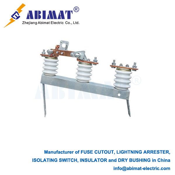
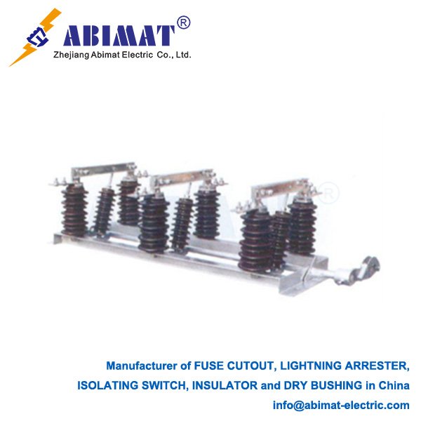
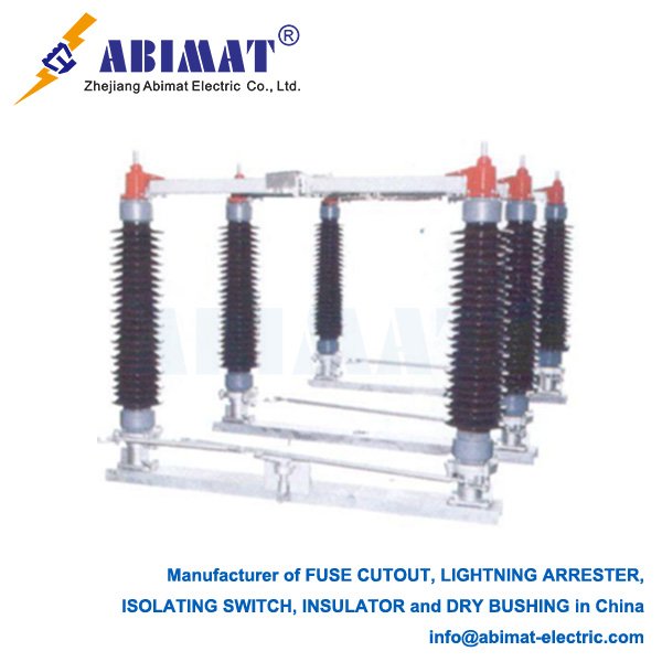
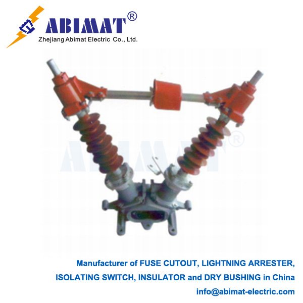
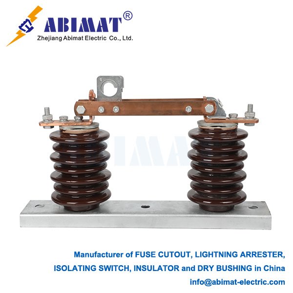
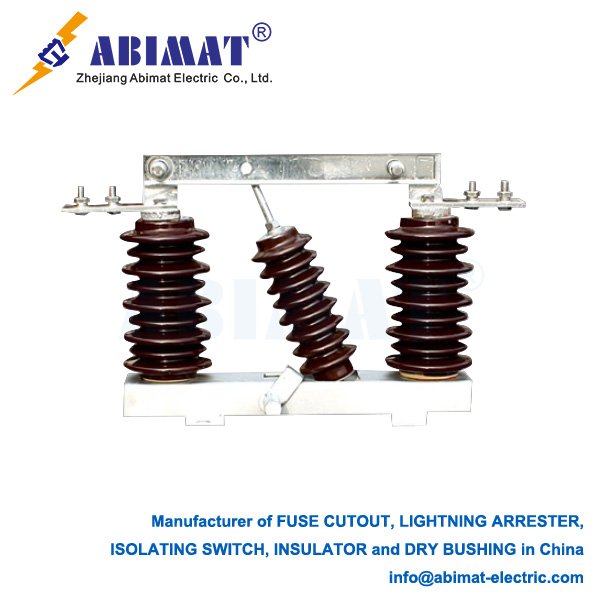
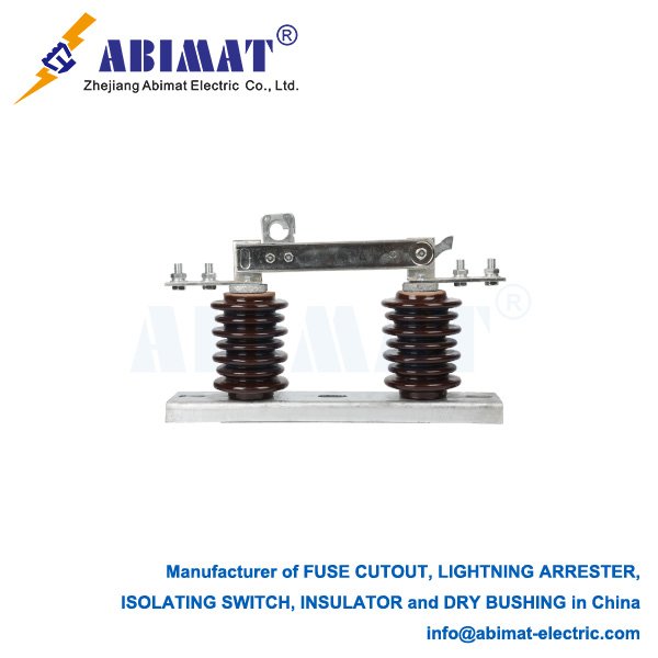
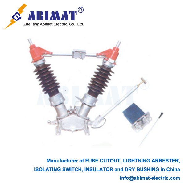
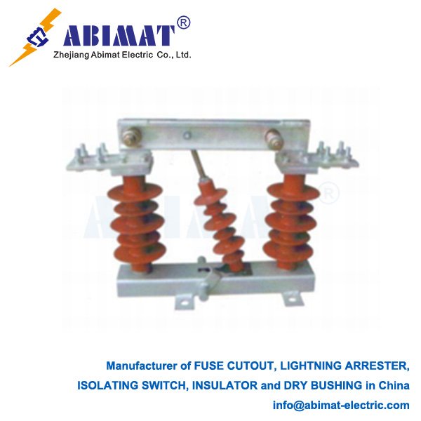
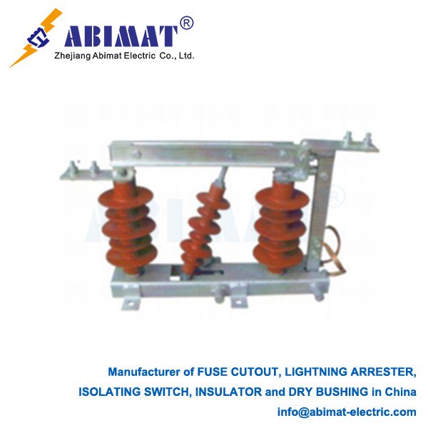
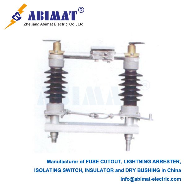
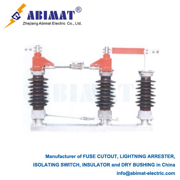
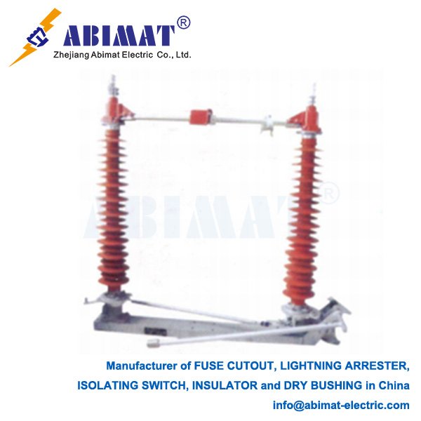
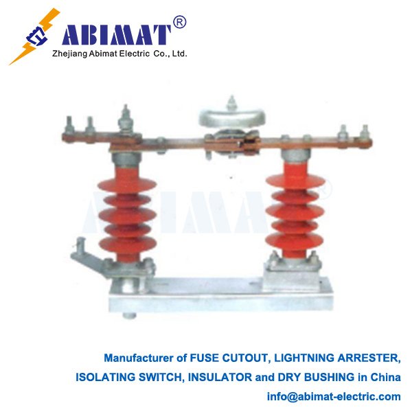
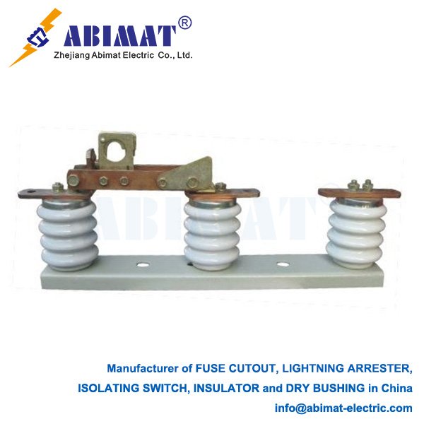
      Line disconnect switches—people also call them isolators—are basic mechanical switching devices we use in electrical power systems. Their main job is to create a safe, visible air gap. We use this gap to isolate a circuit or equipment from the power source. This isolation lets us do maintenance, repairs, or reroute power. They’re critical components; they keep workers safe and help the network run reliably.

    Key Function: Isolation, Not Load Breaking

      We need to tell the difference between disconnect switches and circuit breakers clearly. We don’t design disconnect switches to cut off load current or fault current. We only use them on circuits that an upstream circuit breaker has already de-energized. If we try to open a switch when it’s carrying load, it can create a dangerous electric arc. This arc can damage equipment and cause serious safety risks. The switch’s only purpose is to give a reliable, visible open point. This point lets us confirm a section of the line is de-energized and grounded—so we can work safely.

    Common Types and Configurations

      We use different designs depending on the voltage level and what we need the switch for.

      The horizontal-swing type is the most common one in substations. Its blade rotates horizontally to open or close the circuit.

      Then there’s the vertical-break type. Its blade moves up and down, and we often use it where space is tight.

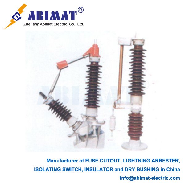
      The center-break type has two rotating blades. These blades separate from the center, and this gives two breaks in a row for higher voltage uses.

      We can operate these switches manually—using a rotating handle and an insulating rod—or with a motor for remote control.

    Critical Components and Features

      A regular disconnect switch has three main parts.

      First is the current-carrying path. It has main blades and contacts, and these parts are made to carry the full system current nonstop.

      Next are the insulators. They hold up the live parts and keep them electrically isolated from the grounded structure.

      Then there’s the operating mechanism. It’s either a manual system or a motorized one, and it opens or closes the blades.

      Many switches also have auxiliary contacts. These connect to the substation’s control system. They show if the switch is open or closed, and they stop unsafe operating steps.

    Applications and Selection Criteria

    We use abimat line disconnect switches everywhere in transmission and distribution networks—from 11kV systems to ultra-high voltage ones. We install them at substation entrances, between bus sections, and to isolate transformers, capacitors, and line segments.
    When we select a disconnect switch, we consider a few factors. One is the rated voltage and current. Another is the short-time withstand current—that’s the ability of the switch to handle fault current for a few seconds when it’s closed. We also consider environmental conditions; for coastal areas, we need anti-corrosion coatings. For cold climates, we need de-icing systems.
    Line disconnect switches may seem simple, but they are extremely important for power system safety and flexibility. We must use them correctly, and we have to follow operating procedures strictly—always ensure we operate them only when the circuit is de-energized. This is crucial to preventing accidents and maintaining grid reliability.
     
  • 11kV Polymer Insulators: Technical Overview

    11kV Polymer Insulators: Technical Overview

    11kV Polymer Insulators: Technical Overview

    Introduction

      11kV polymer insulators—people also call them composite insulators—are key parts in medium-voltage distribution networks. They hold up energized conductors and keep them electrically separate from grounded structures. They can handle different environmental pressures too. These insulators have become widely used because they’re a modern choice instead of traditional porcelain and glass types.

    Structure and Materials

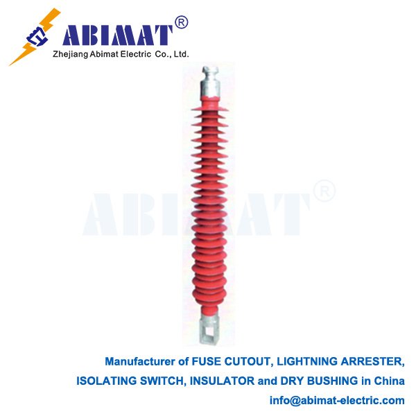
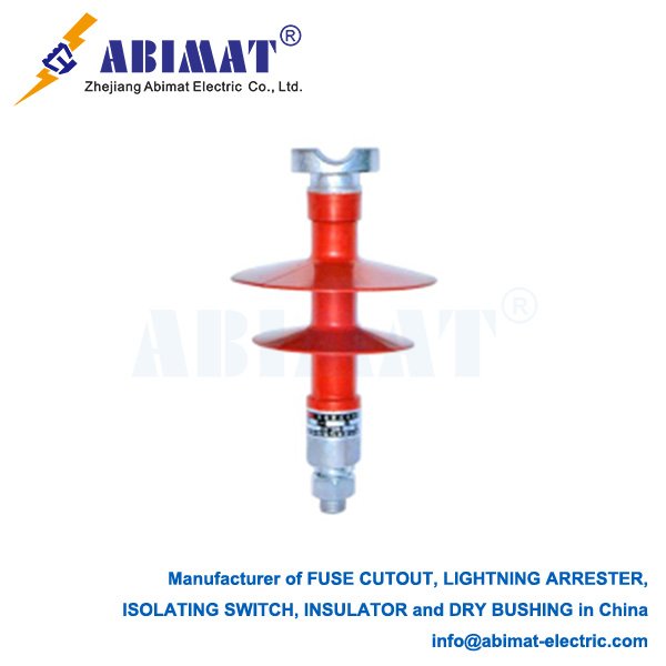
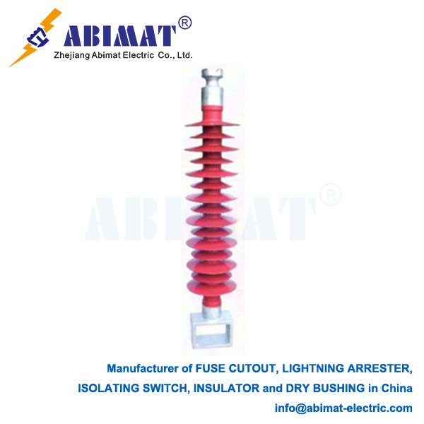
      A typical 11kV polymer insulator has three main parts. The first is the core—it’s a fiberglass reinforced epoxy resin (FRP) rod. This rod gives the insulator high mechanical strength to resist pulling. Next is the weathersheds. These are the outer housing and sheds, made from silicone rubber (SIR) or ethylene propylene diene monomer (EPDM) elastomer. They protect the core from damage caused by the environment, and they also provide the needed leakage distance. The third part is the end fittings. These are metal parts—usually hot-dip galvanized steel or aluminum. Workers crimp them onto the FRP rod, and they’re used to connect the insulator to the support structure and the conductor.

    Key Advantages

      One big advantage is that they’re lightweight. They’re much lighter than porcelain insulators of the same type. This makes them easier to handle, and it also reduces the load on the structures they’re attached to. Another advantage is high resistance to vandalism. The polymer outer layer can take impact without breaking easily. They also have excellent hydrophobicity. The silicone rubber sheds push water away—this stops a continuous conductive water film from forming. This feature lowers leakage current, and it makes the insulators work better in dirty or wet conditions. Plus, they stand up well to UV rays and weather. The modern polymer mixes used to make them are designed for long-term use outdoors.

    Applications in 11kV Systems

      In 11kV systems, people use these insulators for several common jobs. They’re used for suspension and tension on distribution poles—holding the conductors in place and handling pulling forces. They also work as post-insulators for mounting things like distribution transformers, switchgear, and fuse cut-outs. And they’re used as spacers in bundled conductor setups—keeping the conductors apart properly.

    Standards and Testing

      Factories make and test these insulators following international standards. Two common ones are IEC 61972 and IEC 62217. There are several key tests they need to pass. One is mechanical load tests—also called Specified Mechanical Load (SML) tests. Another is power frequency withstand voltage tests. They also have to pass impulse withstand voltage tests. And there are salt fog tests—these check how well the insulators work in polluted conditions.

    Conclusion

      The abimat 11kV polymer insulator combines good mechanical strength, solid electrical performance, and strong resistance to the environment. Its ability to repel water is a big plus—especially for use in coastal areas or places with industrial pollution. It can work reliably for more than 25 years, and it doesn’t need much maintenance.