Author: Zhou

  • Zinc Oxide Surge Arresters: Guardians of Electrical Systems

    Zinc Oxide Surge Arresters: Guardians of Electrical Systems

    Zinc Oxide Surge Arresters: Guardians of Electrical Systems

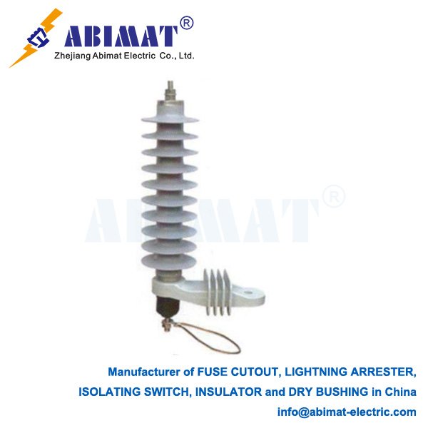
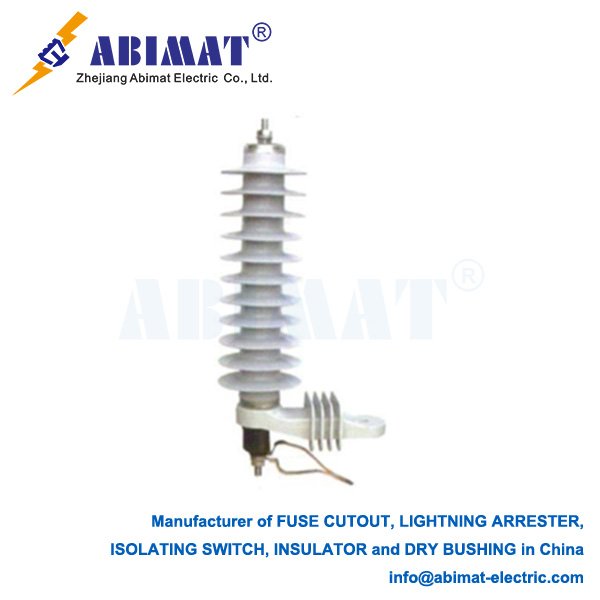
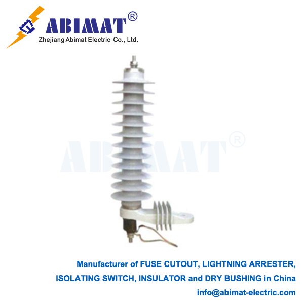
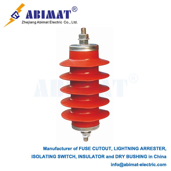
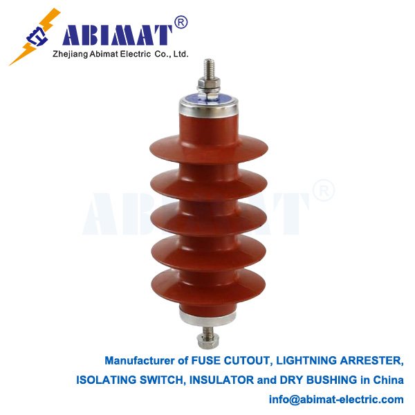
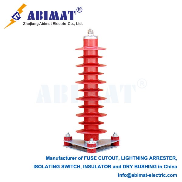
    Surge arresters are indispensable protective devices within electrical power systems, shielding valuable equipment from damaging overvoltages caused by lightning strikes, switching operations, or faults. Among various technologies, the Zinc Oxide (ZnO) surge arrester stands as the modern standard due to its superior performance and reliability.
    The ZnO Revolution: Beyond Traditional Gaps

    Prior to ZnO, silicon carbide (SiC) arresters dominated. These relied on spark gaps in series with SiC resistor blocks. While functional, they suffered limitations: they required series gaps to isolate the system voltage, exhibited a relatively gradual turn-on characteristic, and needed follow current interruption after discharging a surge. The development of ZnO varistor ceramics in the 1970s revolutionized surge protection.

    The Heart: ZnO Varistor Ceramic

    The core component is a bulk ceramic material primarily composed of zinc oxide (ZnO) grains (typically >90%), doped with small amounts of other metal oxides (like Bi₂O₃, Sb₂O₃, CoO, MnO). This unique microstructure is key to its properties. The highly conductive ZnO grains are separated by thin, highly resistive intergranular layers rich in the dopant oxides. These grain boundaries form millions of microscopic “back-to-back Zener diodes” within the bulk material.

    Highly Nonlinear Voltage-Current Characteristic

    This microstructure grants ZnO ceramics an exceptionally nonlinear voltage-current (V-I) characteristic:

       Low Leakage Current: At normal system operating voltage, the arrester presents a very high resistance (MΩ range), drawing only microamperes of leakage current. It remains effectively invisible to the system.

       Sharp Knee Point & Clamping: When an overvoltage exceeding a critical threshold (the “reference voltage”) occurs, the grain boundaries break down dramatically. Resistance drops sharply by several orders of magnitude within nanoseconds. This allows massive surge current (kA) to be diverted safely to earth, while clamping the voltage appearing across the protected equipment to a predictable, limited level – the protective level.

       Instantaneous Recovery: Once the surge passes and voltage returns below the threshold, the grain boundaries instantly regain their high resistance. There is no follow current to interrupt, unlike SiC arresters with gaps.

    Key Advantages of ZnO Arresters

      I. No Series Gaps: Eliminates issues like sparkover delay, contamination sensitivity, and the need for follow current interruption mechanisms. Simplifies design and enhances reliability.
      II. Superior Protection Level: The sharper knee point and lower clamping voltage compared to SiC arresters provide better protection margins for sensitive equipment like transformers and rotating machines.
      III. Faster Response: Responds virtually instantaneously (nanoseconds) to steep-fronted surges, offering superior protection against very fast transients (VFTOs).
      IV. High Energy Absorption Capacity: Modern ZnO blocks can absorb massive amounts of surge energy per unit volume, allowing compact arrester designs even for high-voltage applications.
      V. Excellent Stability: Properly manufactured ZnO varistors exhibit stable characteristics over long service lives under normal operating conditions. Leakage current monitoring provides valuable diagnostic information on aging or contamination.
      VI. Wide Application Range: Available for voltages from low-voltage (LV) residential systems to ultra-high-voltage (UHV) transmission lines (exceeding 1000 kV), and for both AC and DC systems.

    Applications and Design

    ZnO arresters are ubiquitous:

       Transmission & Distribution: Protecting substations (transformers, circuit breakers, busbars) and overhead lines.

       Rotating Machines: Shielding generators and motors from switching surges and lightning.

       Industrial & Commercial Facilities: Safeguarding sensitive process control equipment and building infrastructure.

       Renewable Energy: Critical for protecting wind turbine generators and solar inverters.


    An arrester assembly typically comprises a column of ZnO varistor blocks stacked electrically in series, housed within a robust, weatherproof enclosure. For higher voltages, the housing provides necessary creepage distance. Designs include porcelain-housed arresters (traditional) and polymeric-housed arresters (lighter weight, superior pollution performance, explosion-safe).

    Conclusion

    The Abimat electric Zinc Oxide surge arresters represent a fundamental advancement in overvoltage protection technology. Their unique, gap-less design based on highly nonlinear ZnO varistor ceramics provides fast, reliable, and predictable clamping of dangerous overvoltages. With advantages like superior protective levels, high energy handling, inherent stability, and versatility across voltage classes, ZnO arresters are the cornerstone of modern electrical system resilience, safeguarding critical infrastructure and ensuring operational continuity. Continuous material research and design optimization further enhance their performance and reliability for increasingly complex power grids.
  • Composite Insulators: Advancements in Electrical Insulation Technology

    Composite Insulators: Advancements in Electrical Insulation Technology

    Composite Insulators: Advancements in Electrical Insulation Technology

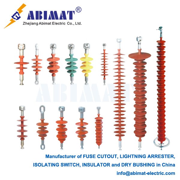
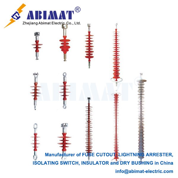
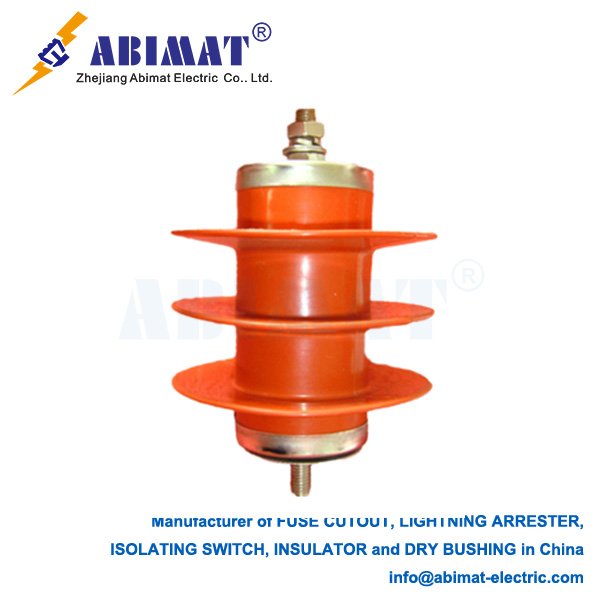
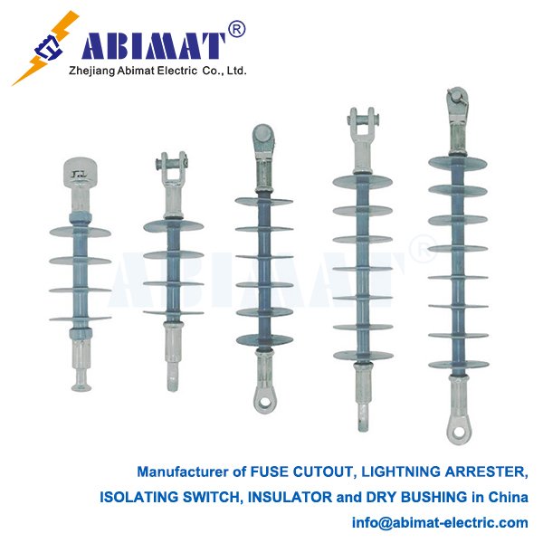
    Composite insulators, formally designated as polymer or non-ceramic insulators (NCIs), constitute a critical innovation in high-voltage insulation for power transmission and distribution systems. Their superior performance in challenging environmental conditions has led to widespread adoption as replacements for conventional porcelain and glass insulators.

    Structural Composition and Materials

    A composite insulator integrates three essential components:

      I. Load-Bearing Core: A fiber-reinforced polymer (FRP) rod, typically epoxy resin reinforced with E-glass or R-glass fibers. This core provides high tensile strength (typically 600-1200 MPa) and serves as the primary dielectric barrier.
      II. Polymeric Housing (Weathersheds): Molded silicone rubber (commonly High-Temperature Vulcanized HTV or Liquid Silicone Rubber LSR) encapsulating the core. Key material properties include:
    Inherent Hydrophobicity: Prevents continuous water film formation on the surface, maintaining insulation integrity under wet contamination. Exhibits hydrophobic recovery and transfer capabilities.
    High Tracking and Erosion Resistance: Withstands surface discharge degradation per IEC 60587 standards.
    Environmental Stability: Resists UV radiation, ozone, and temperature extremes (-50°C to +150°C).
      III. Metal End Fittings: Forged steel, aluminum alloy, or ductile iron terminals crimped or adhesively bonded to the FRP core. Critical seal designs (e.g., triple-seal systems) prevent moisture ingress at the core-end fitting interface.

    Performance Advantages Over Traditional Insulators

       Exceptional Contamination Performance: Hydrophobicity significantly reduces leakage currents and flashover risk in polluted, coastal, or industrial environments, enabling shorter creepage distances and reduced maintenance frequency.

       High Specific Strength: FRP cores achieve tensile strengths exceeding 1000 MPa at 20-30% the weight of equivalent porcelain units, reducing structural loads on support structures.

       Damage Resistance: Resilient polymer housing resists vandalism (e.g., gunshot impact) and mechanical shock without catastrophic failure.

       Seismic Resilience: Lower mass and inherent flexibility enhance performance in earthquake-prone regions.

       Lifecycle Efficiency: Reduced cleaning requirements and elimination of zero-value testing lower operational expenditures.

    Primary Applications

       High-Voltage Transmission Lines: Standard for AC (HV/EHV/UHV) and HVDC systems, particularly in contaminated zones, heavy icing regions, and areas with seismic risk. Enables compact line design.

       Medium-Voltage Distribution Networks: Dominant solution for pole-mounted applications.

       Substations: Bus supports, circuit breaker interrupters, and cable terminations where space or pollution constraints exist.

       Specialized Installations: Railway electrification (25kV AC) and converter stations.

    Critical Considerations

       Long-Term Aging: Performance under combined electrical, mechanical, and environmental stress requires ongoing evaluation per IEC 62217 and IEC 61109 standards. Core brittle fracture and sheath erosion are key failure modes under study.

       Manufacturing Quality: Strict process control is essential for FRP core integrity, silicone rubber formulation consistency, and hermetic end-seal performance.

       Condition Monitoring: Combines visual inspection (for cracks, chalking, brittle core exposure) with diagnostic methods: hydrophobicity classification (STRI Guide 92/1), infrared thermography, and UV corona detection.

    Conclusion

    Abimat Composite insulators, engineered from FRP cores and silicone rubber housings, deliver unmatched technical advantages for modern power networks. Their contamination resistance, high mechanical strength-to-weight ratio, and reduced maintenance requirements provide tangible operational benefits. Continuous material development and adherence to stringent manufacturing protocols ensure their critical role in enhancing grid reliability. As power systems expand into extreme environments, composite insulator technology remains fundamental to transmission efficiency and resilience.

  • Electrical Surge Arresters: Safeguarding Critical Infrastructure

    Electrical Surge Arresters: Safeguarding Critical Infrastructure

    Electrical Surge Arresters: Safeguarding Critical Infrastructure

    In the intricate world of electrical power systems and sensitive electronics, voltage surges pose a constant threat. These transient overvoltages, often caused by lightning strikes, switching operations, or faults, can inflict catastrophic damage on equipment, disrupt operations, and incur significant costs. Electrical Surge Arresters (SAs), also known as Surge Protection Devices (SPDs) in lower voltage contexts, serve as the paramount defense line against these destructive events.

    Core Function and Principle

    An arrester is fundamentally a voltage-activated switch connected in parallel with the equipment it protects, between phase and ground (or phase-to-phase). Under normal operating conditions, the arrester presents a very high impedance (essentially an open circuit), allowing the system voltage to pass unimpeded to the load. However, when a surge voltage exceeding a predetermined threshold (the protective level or let-through voltage) appears, the arrester rapidly “clamps” or limits this voltage to a safe level by switching to a state of very low impedance. This action diverts the massive surge current safely to ground, bypassing the protected equipment. Once the surge subsides and system voltage returns to normal, the arrester automatically regains its high-impedance state.

    Key Components & Technologies

    Modern arresters primarily utilize Metal Oxide Varistors (MOVs) as their nonlinear resistive elements. MOV blocks, composed primarily of zinc oxide (ZnO) grains with intricate additive metal oxides, exhibit exceptional voltage-dependent resistance characteristics. Their highly nonlinear V-I curve enables precise clamping action. Key arrester components include:
       I. MOV Blocks: The core elements providing the nonlinear resistance.
       II. Housing: Typically polymeric (silicone rubber) for lighter weight, pollution resistance, and superior performance, or porcelain in some legacy applications. The housing provides mechanical integrity and environmental protection.
       III. Sealing System: Prevents moisture ingress, critical for long-term reliability.
       IV. Terminals: For connection to the system and ground.
       V. Internal/Ground Lead: Conducts surge current to ground. Low impedance grounding is crucial for arrester effectiveness.

    Critical Technical Parameters

    Selecting and applying arresters requires careful consideration of several parameters:

       Rated Voltage (Ur): The maximum permissible continuous operating voltage (power frequency) across the arrester terminals.

       Continuous Operating Voltage (Uc): The RMS value of the maximum power-frequency voltage that can be continuously applied.

       Nominal Discharge Current (In): The peak value of the current wave (8/20 µs) used to classify the arrester’s duty cycle.

       Maximum Discharge Current (Imax): The peak value of the highest standard 8/20 µs current wave the arrester can withstand at least once without damage.

       Protection Level (Up): The maximum residual voltage magnitude developed across the arrester terminals when discharging specified currents (e.g., In, Imax). This is the clamped voltage seen by the protected equipment and is the single most critical parameter for insulation coordination.

       Energy Handling Capability: The ability to absorb the Joule heating energy from surges without degradation.

       Pressure Relief: Design feature (especially in porcelain housings) to safely vent internal gases during a rare catastrophic failure, preventing violent rupture.

    Applications Across the Spectrum

    ABIMAT surge arresters are ubiquitous throughout electrical systems:

       High Voltage Transmission & Substations: Protecting transformers, circuit breakers, buswork, and other primary equipment from lightning and switching surges. These are typically station-class arresters.

       Medium Voltage Distribution: Safeguarding feeders, pole-mounted transformers, switchgear, and capacitors. Distribution-class arresters are common.

       Low Voltage Systems: Protecting buildings, industrial control systems, data centers, and sensitive electronic equipment at the service entrance and point-of-use levels (SPDs). These often incorporate additional technologies like gas discharge tubes.

    Selection & Maintenance

    Proper selection involves matching the arrester’s Ur, Uc, Up, and energy capability to the system voltage, insulation levels (BIL/SIL), and the anticipated surge environment (location, lightning density). Regular maintenance, including visual inspections for damage or pollution, thermographic scanning for hot spots indicating degradation, and periodic leakage current monitoring, is essential to ensure continued reliability.

    Conclusion

    Electrical surge arresters are indispensable guardians of modern electrical infrastructure. By reliably clamping transient overvoltages and diverting destructive surge currents to ground, they prevent equipment failure, enhance system reliability, minimize downtime, and protect significant investments. Understanding their operating principles, key technologies, and critical parameters is fundamental for engineers designing, operating, and maintaining safe and resilient power systems and electronic installations. Continuous advancements in MOV technology and polymeric housing design further improve their performance, longevity, and safety.

  • 345 kV Disconnecting Switches: Critical Components for EHV Grid Security

    345 kV Disconnecting Switches: Critical Components for EHV Grid Security

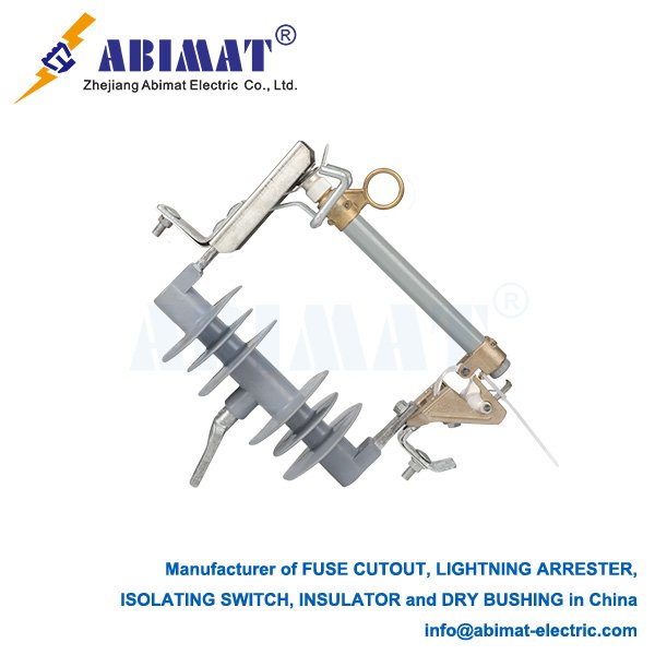
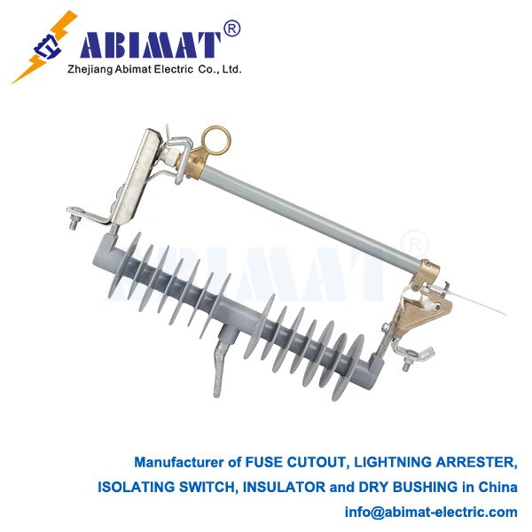
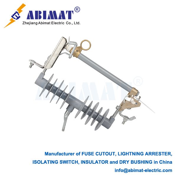
    Dropout Fuse Cutout Covers: Critical Protection for Distribution Systems 

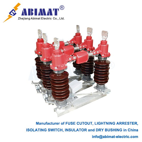
    345 kV disconnecting switches (DS) serve as vital isolation devices in extra-high-voltage transmission networks, enabling safe maintenance, circuit reconfiguration, and fault isolation. Their design addresses unique challenges at this voltage class, where switching overvoltages, corona effects, and seismic forces demand engineered solutions.  

    Core Technical Requirements

    I. Dielectric Integrity
    – Air Clearance: Minimum 2.9 m phase-to-ground (IEEE Std 1527)
    – Creepage Distance: ≥25 mm/kV (RTV silicone-coated insulators)
    – BIL Rating: 1300 kV lightning impulse withstand
    – Corona Control: Radio-influence voltage (RIV) <500 μV at 1.1× operating voltage

    II. Mechanical Performance
    – Operating Torque: 150–300 N·m for rotating-arm designs
    – Ice Breaking: Capable of operating under 20 mm radial ice (IEC 62271-102)
    – Seismic Rating: 0.5g PGA (peak ground acceleration) without damage

    Advanced Design Features

    Contact Systems  

    – Self-aligning tulips: Copper-chromium-zirconium (CuCrZr) alloy contacts maintain ≤50 μΩ resistance after 10,000 operations  

    – Arcless auxiliary contacts: Pre-insertion resistors limit VFTO (Very Fast Transient Overvoltage) <1.5 p.u.  


    Insulation Coordination  

    – Composite insulators: FRP core with hydrophobic silicone sheds (leakage distance: 9,300 mm)  

    – Grading rings: Optimized diameter-to-tube ratio (1:2.5) controls electric field <15 kV/cm  

    Failure Modes & Mitigation

    RiskDetection MethodPreventive Measure
    Contact oxidationΔR >100 μΩ (online monitoring)Nitrogen-filled contact chambers
    Insulator pollutionESDD >0.05 mg/cm² (insp.)Periodic RIV testing
    Mechanical bindingTorque >350 N·mAnti-icing heaters (-40°C rating)
    VFTO damagedV/dt >5 kV/ns measurementSnubber circuits across contacts

    Smart Switching Innovations

    – Condition monitoring: Integrated sensors track:  

      – Contact temperature (Fiber Bragg Grating)  

      – Motor current signature analysis (MCSA)  

      – Partial discharge >5 pC sensitivity  

    – Digital twins: ANSYS-based simulation predicts contact erosion within 3% accuracy  

    – Robotic operation: Remotely operated crawlers for hazardous environments  

    Testing & Compliance

    – Type tests per IEC 62271-102:  

      – 1000 mechanical operations at -40°C to +40°C  

      – Short-circuit withstand: 40 kA/3s (rated) to 63 kA/1s (design)  

      – Radio interference voltage (RIV) testing at 1.1× 362 kV  

    – Seismic validation: Shake-table testing with IEEE 693 protocols  

    Conclusion

    345 kV disconnecting switches balance electrical robustness with mechanical precision. Modern designs integrate monitoring and adaptive control, transforming passive components into intelligent grid assets. As renewables drive grid reconfiguration frequency upward, next-gen switches with predictive diagnostics and reduced VFTO will become critical for EHV network resilience. ABMAT electric report 0.0007% forced outage rates with monitored switches—40% lower than conventional units.

  • Dropout Fuse Cutout Covers: Critical Protection for Distribution Systems 

    Dropout Fuse Cutout Covers: Critical Protection for Distribution Systems 

    Dropout Fuse Cutout Covers: Critical Protection for Distribution Systems 

    Dropout fuse cutouts (DFCs) serve as vital overcurrent protection devices in medium-voltage distribution networks (typically 15–38kV). Their polymer covers—often overlooked—play essential roles in safety enhancement, equipment longevity, and system reliability. This article examines the technical functions, design evolution, and operational imperatives of these components.  

     Core Functions of Cutout Covers  

    1. Arc Containment  

       During fuse operation, polymer covers withstand internal arcs >10kA/0.1s. Materials like glass-reinforced polyester (GRP) or thermoplastic elastomers (TPE) provide:  

       – Arc resistance up to 180°C continuous  

       – Tracking resistance >600 V per IEC 60587  

       – Containment of molten metal ejecta  


    1. Environmental Sealing  

       IP67-rated covers prevent:  

       – Moisture ingress (critical for coastal/high-humidity zones)  

       – Salt/chemical contamination reducing creepage distance  

       – Ice accumulation disrupting dropout mechanism  


    1. Wildlife Protection  

       Covers with smooth profiles and insulating skirts reduce animal-caused outages by 92% (EPRI study). Features include:  

       – 360° ribbed barriers against squirrels/snakes  

       – UV-stabilized coatings (>20-year service life)  

    Material & Design Evolution

    Generational Shifts:  

    EraMaterialKey AdvancementLimitation
    1980s-90sPorcelainHigh compressive strengthBrittle fracture risk
    2000sEPDM RubberElastic recovery >85%Ozone degradation
    2010s+Silicone CompositeHydrophobicity recovery <5minHigher cost

    Modern designs incorporate:  

    – Pressure-relief vents: Direct arc gases upward at 30° angle  

    – Dual-durometer seals: Hard inner frame + soft outer gasket  

    – RFID tags: Enabling asset tracking via handheld scanners

    Failure Modes & Maintenance Protocols

    Critical Risks from Damaged Covers:  

    – Flashover Events: Cracks >3mm allow moisture paths, reducing BIL by 40%  

    – Fuse Non-Dropout: Corroded hinges increase operating torque beyond 50 N·m  

    – Phase-to-Phase Faults: Missing covers invite bird bridging (85% of avian outages)  


    Inspection Standards (per ANSI C37.41):  

    1. Infrared thermography: ΔT >15°C indicates internal degradation
    2. Hydrophobicity testing: HC1–HC7 classification per IEC 62073  

    III. Mechanical force test: Verify hinge torque <35 N·m annually  

    Smart Cover Innovations

    Leading manufacturers now integrate:  

    – Wireless CT sensors: Monitor leakage current >10mA  

    – Self-tightening mechanisms: Shape-memory alloys compensate for seal compression  

    – Photocatalytic coatings: TiO₂ nanoparticles decompose organic pollutants  

    Standards Compliance

    Complies with:

    – IEC 60099-4 (Metal-oxide surge arresters)

    – IEEE C62.11 (Standard for MOV arresters)

    – ANSI/IEEE C62.22 (Application guide)

    Failure Mechanisms

       Moisture Ingress: Degrades MOV blocks (detected via rising leakage current)

       Thermal Runaway: Caused by continuous overvoltage or contamination

       Energy Overstress: Exceeding rated kJ capacity

       Seismic Damage: Cracked porcelain/polymer housings

    Conclusion

    The ABIMAT Dropout fuse cutout covers transcend simple environmental shields—they are engineered safety systems preventing cascading failures. With utilities facing increased wildfire risks and storm hardening mandates, next-generation covers combining real-time monitoring, self-healing materials, and enhanced arc containment will become grid resiliency cornerstones. Proper maintenance remains critical: a $200 cover replacement prevents average $18,000 outage costs (IEEE 1366 data).

  • 33 kV Lightning Arresters: Protection Against Transient Overvoltages

    33 kV Lightning Arresters: Protection Against Transient Overvoltages

    33 kV Lightning Arresters: Protection Against Transient Overvoltages

    33 kV lightning arresters are essential components in medium-voltage power systems, safeguarding equipment from damaging voltage surges caused by lightning-induced and switching transients. These devices protect transformers, switchgear, and cables by limiting overvoltages to safe levels.

    Operational Principle

    Arresters perform three critical functions:
    I. Voltage Monitoring: Maintain high impedance during normal system operation (33 kV phase-to-phase)
    II. Surge Diversion: Instantaneously switch to low impedance during overvoltages, channeling surge current to earth
    III. Voltage Clamping: Maintain residual voltage below the protected equipment’s Basic Insulation Level (BIL)
    IV. System Recovery: Automatically restore high-impedance state after surge events

    Key Technical Parameters

       Rated Voltage (Ur): 30-36 kV (system-dependent), exceeding maximum continuous operating voltage

       MCOV (Maximum Continuous Operating Voltage): 24-28 kV RMS (prevents thermal runaway)

       Duty Class: Station (highest energy handling), Intermediate, or Distribution

       Nominal Discharge Current (In): 5kA, 10kA, or 20kA (standard test rating)

       Residual Voltage (Ures): Voltage at specified current (e.g., 10kA 8/20µs wave). Must be ≤85% of protected equipment BIL (typically 170-200 kV)

       Energy Rating: kJ/kV Ur capacity (determines multi-surge withstand)

       Pressure Relief: Withstands internal faults without casing rupture

    Zinc Oxide (MOV) Technology

    Modern 33 kV arresters employ gapless metal-oxide varistor technology:

    – Non-linear Characteristics: Exponential voltage-current relationship

    – Nanosecond Response: Faster operation than gapped designs

    – High Energy Density: Superior kJ absorption per unit volume

    – Hermetic Sealing: Prevents moisture ingress and contamination

    – Monitoring Provisions: Terminal for leakage current measurement

    Selection Criteria

    1. System Parameters: Temporary overvoltages, fault current magnitude
    2. Protected Equipment: Transformer/reactor BIL ratings

    III.  Location Criticality:  

        – Station class: Substation entrances, generator terminals  

        – Distribution class: Pole-mounted applications

    1. Environmental Conditions:  

        – Pollution severity (determines creepage distance: ≥31 mm/kV for Class IV)  

        – Altitude (>1000m requires derating)  

        – Seismic zone requirements

    1. Short-Circuit Withstand: Pressure relief capacity > available fault current
    2. Monitoring Needs: Leakage current measurement ports

    Installation Requirements

       Proximity: Mount directly adjacent to protected equipment

       Earthing: Establish low-impedance earth connection (<5 Ω)

       Conductor Practice:  

        – Keep lead lengths minimal  

        – Employ short, straight conductors  

        – Avoid sharp bends in downconductors

       Clearances: Maintain phase-to-phase/ground distances per IEC 61936

       Orientation: Install vertically unless designed for horizontal mounting

    Maintenance & Monitoring

       Visual Inspection: Quarterly checks for:  

        – Housing damage (cracks, tracking)  

        – Seal integrity  

        – Corrosion/birdcage damage

       Leakage Current Measurement:  

        – Baseline reading at commissioning  

        – Trend resistive component (>20% increase indicates degradation)

       Thermal Imaging: Annual IR scans under load

       Diagnostic Testing:  

        – Insulation resistance (>1000 MΩ)  

        – Reference voltage tests (per OEM schedule)

    Standards Compliance

    Complies with:

    – IEC 60099-4 (Metal-oxide surge arresters)

    – IEEE C62.11 (Standard for MOV arresters)

    – ANSI/IEEE C62.22 (Application guide)

    Failure Mechanisms

       Moisture Ingress: Degrades MOV blocks (detected via rising leakage current)

       Thermal Runaway: Caused by continuous overvoltage or contamination

       Energy Overstress: Exceeding rated kJ capacity

       Seismic Damage: Cracked porcelain/polymer housings

    Conclusion

    Properly specified 33 kV metal-oxide arresters provide critical protection against transient overvoltages in medium-voltage systems. Their non-linear characteristics and rapid response ensure sensitive equipment remains within safe voltage tolerances during surge events. Rigorous adherence to installation practices, regular leakage current monitoring, and compliance with IEC/IEEE standards are fundamental to achieving reliable, long-term system protection and preventing catastrophic equipment failure.

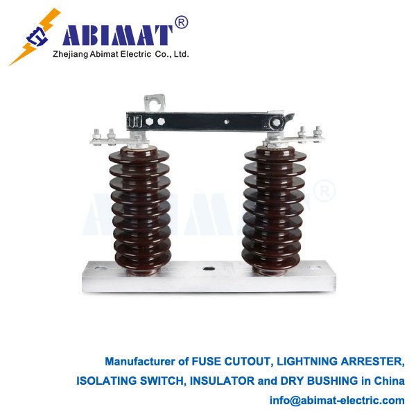
  • 138 kV Disconnect Switches: Essential Components for Power System Safety and Flexibility

    138 kV Disconnect Switches: Essential Components for Power System Safety and Flexibility

    138 kV Disconnect Switches: Essential Components for Power System Safety and Flexibility

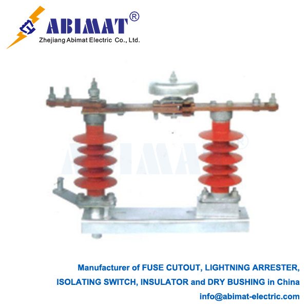
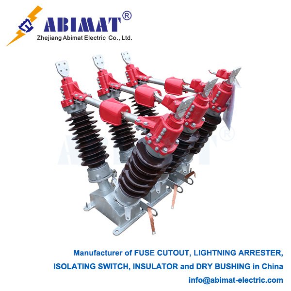
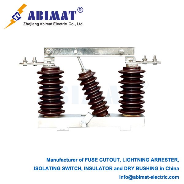
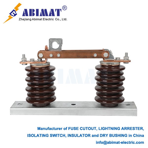
    In high-voltage transmission and substation infrastructure, the 138 kV disconnect switch (commonly known as an isolator) is a fundamental component. Operating at a critical transmission voltage, these robust devices provide vital safety and operational functions distinct from circuit breakers.

    Core Function: Visible Isolation

    The primary purpose of a 138 kV disconnect switch is to establish visible physical isolation through an air gap. When fully open, the separated blades create a clear break in the circuit. This isolates specific equipment—transformers, bus sections, lines, or circuit breakers—from live sections elsewhere. This isolation serves two critical purposes:


    I. Personnel Safety: Provides a verifiable de-energized state for maintenance, inspection, or repair work downstream. The visible gap offers essential safety confirmation beyond relying solely on relay indicators or control systems.

    II. Operational Flexibility: Enables network reconfiguration for load transfers, sectionalizing during faults, or routing power through alternative paths without de-energizing entire substations.


    Operational Characteristics and Design

       Voltage Rating: Designed for 138 kV systems with rigorous dielectric withstand capabilities for power frequency and impulse voltages.

       Current Rating: Engineered to carry maximum continuous load current without exceeding temperature limits and withstand specified short-circuit currents for defined durations (e.g., 3 seconds).

       Switching Limitation: Standard disconnect switches cannot interrupt load or fault current. Operating under load creates destructive arcs. They function only after an upstream circuit breaker has de-energized the circuit.

       Specialized Interruption: Some designs incorporate arcing horns or chambers to interrupt minimal charging currents (e.g., unloaded bus sections) or controlled loop currents, as defined by manufacturers and standards (IEEE C37.30, IEC 62271-102).

       Mechanical Design: Built for reliability and longevity in outdoor environments. Common configurations include:

           Center-Break: Horizontally rotating insulators move a central blade.

           Vertical-Break (Single/Double): Blades pivot vertically, offering compact footprints and better ice-shedding capability.

           Pantograph: Scissor-like mechanism for vertical reach, ideal for bus transfers.

       Operation: Manual (via insulated rods/cranks) or motorized actuators (for remote/SCADA integration).

    Critical Safety Systems

        Interlocks: Mandatory mechanical/electrical locks prevent unsafe operations, primarily blocking disconnect switch opening while its associated circuit breaker is closed. Additional interlocks may restrict access to live compartments.

       Grounding Switches: Often integral or directly associated. These provide a visible means to safely ground the isolated section before work begins, protecting personnel from induced voltages or accidental re-energization. Interlocks prevent simultaneous closure of disconnect and grounding switches.

    Selection Criteria

    Selection requires careful assessment of:

       Continuous Current Rating

       Short-Time Withstand Current (kA) and Duration

       Rated Voltage and Dielectric Strength (BIL)

       Switching Capability (if applicable: capacitive, loop)

       Environmental Conditions (wind, ice, seismic, pollution)

       Configuration Type (center-break, vertical-break, pantograph)

       Control Method (manual, motorized)

       Compliance with IEEE C37 series or IEC 62271 standards.

    Maintenance Imperative

    Routine inspection and maintenance ensure long-term reliability:

       Verify blade alignment and contact pressure

       Ensure smooth mechanism operation

       Inspect insulators for damage/contamination

       Test interlocks

       Maintain proper lubrication

    Conclusion

    The ABIMAT 138 kV disconnect switch is a critical element for power system safety and flexibility. By providing unambiguous physical isolation and enabling safe work practices through visible gaps and grounding, it protects personnel and supports reliable transmission network operation. Its robust construction ensures decades of performance under demanding electrical and environmental conditions.

  • 15 kV Disconnect Switches: Ensuring Safety and Control in Medium-Voltage Systems

    15 kV Disconnect Switches: Ensuring Safety and Control in Medium-Voltage Systems

    15 kV Disconnect Switches: Critical Components for Medium-Voltage System Safety

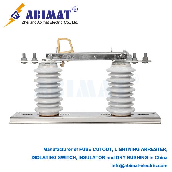
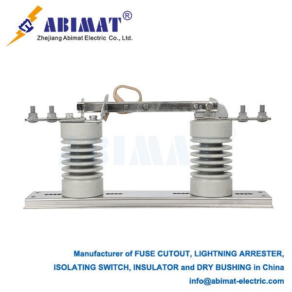
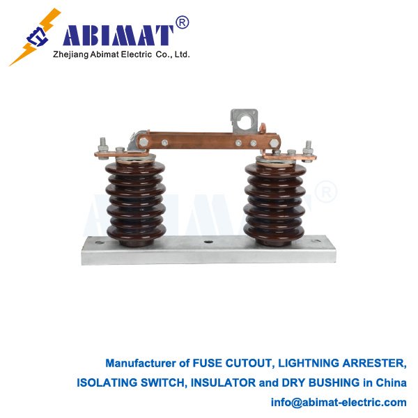
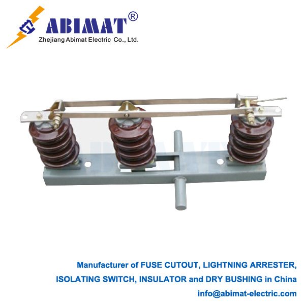
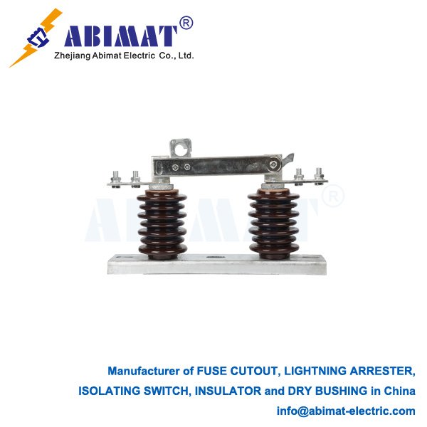
    15 kV disconnect switches serve as fundamental safety devices in industrial power distribution, utility substations, and commercial electrical networks. Operating at medium-voltage levels, these components provide essential isolation functions for maintenance safety and system operation.

    Primary Function: Visible Circuit Isolation

    The core purpose of a 15 kV disconnect switch is to establish a visible air gap in the circuit. When open, separated contacts create unambiguous physical isolation between de-energized equipment and live sections. This fulfills critical requirements:


    I.Personnel Protection: Creates a verifiable de-energized state for safe maintenance of downstream equipment (transformers, capacitors, feeders).

    II.Operational Control: Enables circuit sectionalization, load transfers, and system reconfiguration without full network de-energization.

    Design and Operational Characteristics

       Voltage Rating: Designed for 15 kV systems with dielectric strength to withstand operating voltage, temporary overvoltages, and lightning impulses (standard BIL ratings: 95 kV, 110 kV, 125 kV).

       Current Rating: Carries continuous load currents (typically 600A, 1200A, 2000A) without excessive temperature rise. Withstands specified short-circuit currents (e.g., 25-40 kA for 1-4 seconds).

       Switching Limitation: Standard disconnect switches cannot interrupt load or fault current. Operation under load causes destructive arcing. They operate only after upstream circuit protection clears the circuit.

       Specialized Interruption: Certain designs incorporate arcing horns to break minimal capacitive charging currents (unloaded cables/bus sections) per IEEE C37.34.

       Configuration Types:

           Indoor (Switchgear): Horizontal-drawout or vertical-break types within arc-resistant metal-clad compartments.

           Outdoor: Vertical-break designs on poles/structures with weather-resistant construction.

           Loadbreak Versions: Integrated vacuum interrupters enable load current interruption (disconnect-loadbreak combos).

       Operation: Manual via rotary handle, lever, or push-pull rod (often spring-assisted). Motorized operators enable remote/SCADA control.

    Safety Systems

       Mechanical Interlocks: Prevent critical errors:

           Opening disconnects with closed circuit breakers

           Racking switches into energized compartments

           Accessing live sections during maintenance

           Closing grounding switches while disconnects are engaged

       Grounding Provisions: Integral or companion grounding switches provide visible earthing of isolated sections, protecting against induced voltages.

       Position Indication: Clear visual “OPEN”/”CLOSED” indicators.

    Selection Criteria

    Key selection factors:

       Environment: Indoor (switchgear) vs. outdoor (pole/pad-mount)

       Electrical Ratings: Continuous current, short-circuit withstand (kA/s), BIL

       Duty Requirement: Isolation only or capacitive current switching

       Mechanical Endurance: Required operating cycles

       Site Conditions: Altitude, pollution, temperature, seismic zone

       Control Method: Manual or motorized actuation

       Compliance: IEEE C37.20.2 (Switchgear), C37.34 (Disconnects), or IEC 62271-102

    Maintenance Imperative

    Essential maintenance ensures reliability:
    I.Contact Inspection: Verify alignment and erosion
    II. Insulator Check: Detect cracks or contamination
    III. Mechanical Test: Confirm smooth operation and full engagement
    IV. Interlock Verification: Validate all safety sequences
    V. Lubrication: Apply manufacturer-specified lubricants

    Conclusion

    The ABIMAT 15 kV disconnect switch remains indispensable for medium-voltage system safety. Its visible isolation capability protects personnel during maintenance while enabling operational flexibility. Robust construction, adherence to safety standards (particularly interlocks and grounding), and disciplined maintenance ensure reliable long-term performance in industrial and utility applications.

  • Zinc Oxide Surge Arresters: Essential Overvoltage Protection Technology

    Zinc Oxide Surge Arresters: Essential Overvoltage Protection Technology

    Zinc Oxide Surge Arresters: Essential Overvoltage Protection Technology

    Operating Principle

    Zinc Oxide (ZnO) surge arresters utilize polycrystalline ceramic varistors exhibiting highly nonlinear voltage-current characteristics. The microstructure comprises ZnO grains (10-50μm) with bismuth-rich intergranular layers forming Schottky barriers. Key electrothermal behavior:  

    – Below threshold: High resistance state (leakage current <1mA at 0.8U<sub>c</sub>)  

    – Above threshold: Exponential conduction (α = 30-50 in I∝V<sup>α</sup> relationship)  

    – Response time: <100ns for 1kV/μs wavefront

    Technical Specifications

    ParameterTransmission ClassDistribution Class
    Rated voltage (U<sub>r</sub>)72-756 kV3-36 kV
    Continuous op. voltage (U<sub>c</sub>)58-605 kV2.4-28.8 kV
    Residual voltage (8/20μs)≤1.8 p.u. of U<sub>r</sub>≤2.0 p.u. of U<sub>r</sub>
    Energy withstand10-40 kJ/kV U<sub>r</sub>4-8 kJ/kV U<sub>r</sub>
    Pressure relief rating40 kA asym. (IEC Class 3)20 kA asym. (IEC Class 2)


    Construction Types

    Porcelain-housed (IEC 60099-4 Type 3):  

    – Alumina porcelain shell (IP66)  

    – Grading rings for uniform field distribution  

    – Explosion diaphragm: 0.5MPa activation pressure  

    – RIV suppression: <500μV at 1MHz  


    Polymer-housed (IEC 60099-4 Type 4):  

    – Filament-wound FRP core  

    – HTV silicone rubber housing (500mm/kV creepage)  

    – Seismic capability: 0.5g @ 3Hz (IEC 61166)  

    – Torsional strength: ≥250 N·m  

    Protection Performance

    Insulation Coordination:  

    – ABIMAT Lightning impulse (1.2/50μs): Protective level ≤ BIL × 0.8  

    – ABIMAT Switching surge (250/2500μs): Residual ≤ 1.3 p.u.  

    – Steep-front (1/5μs): Voltage overshoot ≤ 1.15×residual  

    Stability Criteria:  

    – Power loss: ≤10W at U<sub>c</sub>  

    – Thermal runaway threshold: 1.05-1.10 × U<sub>c</sub>  

    – Energy absorption limit: 300-800 J/cm³

    Application Guidelines

    Transmission Systems (≥115kV):  

    – Substation entrance protection: U<sub>r</sub> ≥ 0.8 × system max voltage  

    – Transformer protection: Residual < 0.85 × BIL  

    – Line discharge class: LDC 2 per IEC 60099-4  

    Distribution Networks (≤36kV):  

    – Pole-mounted installation: U<sub>c</sub> ≥ 1.05 × nominal voltage  

    – Cable termination protection: Shield voltage limiter (SVL) coordination  

    – Critical clearance: Arrester lead length < 1.5m  

    Industrial Applications:  

    – VFD motor protection: dU/dt ≤ 1000V/μs capability  

    – GIS integration: Shielded design for uniform field  

    – TOV withstand: 1.4 × U<sub>c</sub> for 10 seconds

    Condition Monitoring

    Leakage Current Analysis:  

    – Resistive component (I<sub>R</sub>): Baseline <50μA  

    – Third harmonic increase: >200μA indicates degradation 

    – Phase angle shift: >30° deviation requires inspection  

    Field Test Protocol (NETA ATS-2021):  

    I. Insulation resistance: >10,000 MΩ @ 5kV DC
    II. Power frequency reference voltage: ΔV ≤ ±2%
    III. RIV measurement: <500μV @ 0.5-2MHz
    IV. Infrared thermography: ΔT ≤5K phase-phase

    Failure Mechanisms

    MechanismRoot CauseMitigation
    Moisture ingressSeal degradationTriple O-ring sealing system
    Thermal runawayVaristor agingOnline U<sub>c</sub> monitoring
    Housing fractureCantilever load >500NFRP core with strain gauges
    Pollution flashoverNSDD >0.35mg/cm²Hydrophobic HTV silicone

    Technological Evolution

    – Series-gap designs: Enhanced TOV capability (1.5×U<sub>c</sub>/1hr)  

    – IoT monitoring: GSM-based leakage current transmitters  

    – Grading control: SiC nonlinear grading rings  

    – Eco-designs: Dry-air insulation replacing SF<sub>6</sub>  

    Standards Compliance

    – IEC 60099-4:2022 Metal-oxide surge arresters  

    – IEEE C62.11-2020 Standard for MO surge arresters  

    – ANSI/IEEE C62.22-2021 Application guide  

    – EN 60099-4:2014/A1:2019 (TOV requirements)

  • Distribution Cutout: Critical Overhead Line Protection System

    Distribution Cutout: Critical Overhead Line Protection System

    Distribution Cutout: Critical Overhead Line Protection System

    Operational Principle & Functional Design 

    The ABIMAT distribution cutout serves as a fused isolation device in 15-38kV overhead distribution networks. This single-phase assembly integrates three core functions:  

    Overcurrent protection via current-limiting fuse links  

    Visible circuit isolation through gravity-operated drop-out mechanism  

    Network sectionalization for fault confinement  

    Fault interruption sequence:  

    I.Downstream fault generates overcurrent (typically 5-20kA RMS)  

    II.Fusible element melts per defined time-current characteristic (IEC 60282-1)  

    III.Expulsion tube vents arc plasma through deionizing gas generation  

    IV.Pivot mechanism releases fuse holder, rotating >45° from vertical  

    V.Established air gap (>300mm) provides visual isolation confirmation  

    Key Technical Parameters

    CharacteristicStandard Requirement
    Rated Voltage15kV/27kV/38kV (ANSI C37.42)
    Continuous Current100A-300A
    Symmetrical Interrupting Rating10kA (Type K fuse)
    Basic Impulse Level110-150kV BIL
    Fuse Speed ClassificationT (slow), K (fast)

     Primary Protective Functions  

    Fault Containment  

    Isolates transformer internal faults (winding shorts, bushing failures)  

    Clears lateral line faults (animal/vegetation contact, lightning surges)  

    Prevents upstream protection operation for downstream faults  


    Transformer Protection  

    Standard primary-side installation (≥95% of pole-mounted units)  

    Coordination with secondary fuses (100:1 current ratio)  

    Bay-O-Net® dual-element fuse links provide:  

      Instantaneous operation for internal faults (low-current protector link)  

      Time-delayed clearance for through-faults (high-current backup link)  


    Network Sectionalizing  

    Limits outage scope to 3-8 customers per device  

    Reduces SAIDI (System Average Interruption Duration Index) by 25-40%  

    Visual fault indication enables crew response within 30 minutes  

     Technological Evolution  

    Conventional Designs  

    – Porcelain insulators (Pollution Class III per IEC 60815)  

    – Tin-plated copper contact systems  

    – Mechanical drop-out indication  


    Modern Advancements  

    Polymer-housed units: UV-stabilized silicone rubber (IEC 62271-201)  

    Electronic Cutouts (EFC):  

      – GSM/LoRaWAN remote fault reporting  

      ±1% accuracy fault current recording  

      – Adaptive coordination with reclosers  

    Solid-material fuse links: Silver-graphite matrix prevents oxidation failure  

     Maintenance & Reliability Analysis  

    Failure ModePrevalenceEngineering Solution
    Moisture ingress42%Compression-molded silicone gaskets
    Contact degradation28%Silver-nickel plating (100μm min)
    Nuisance operation18%Solid-matrix fuse technology
    Mechanism binding12%Ice-breaking pivot (IEC 60068-2-75)

    Field Validation Protocol  

    I. Thermographic inspection (ΔT ≤5°C between phases)  

    II. Operating torque verification (≤50 N·m)  

    III. Insulation resistance measurement (>1000 MΩ at 5kV DC)  

    IV. Fuse continuity check (4-wire microhmmeter)  


     Industry Application Metrics  

    Deployment density: 8-12 units per circuit mile  

    Transformer protection: 63% reduction in replacement costs  

    Fault clearance: 3-20 cycles (reclosers: 30+ cycles)  

    Service life: 40+ years (porcelain), 25 years (polymer)  

    Technology Evolution

    – Motorized operation: SCADA-integrated actuators  

    – Condition monitoring: Embedded temperature/position sensors  

    – Hybrid switchgear: Vacuum interrupter integration for load-break capability  

    – GIS variants: SF₆-insulated compact designs