Author: Zhou

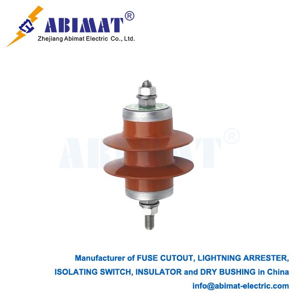
  • Distribution Arrester: Essential Protection for Electrical Networks

    Distribution Arrester: Essential Protection for Electrical Networks

    Distribution Arrester: Essential Protection for Electrical Networks

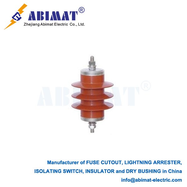
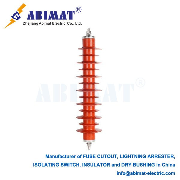
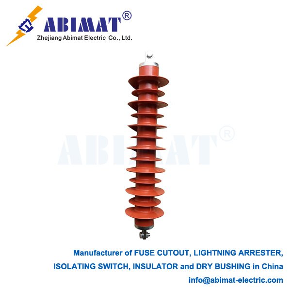
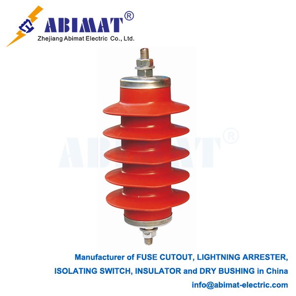
      A distribution arrester—people also call it a surge arrester—is an important protective device. You put it on electrical distribution systems, usually systems that go up to 36kV. Its main job is to protect expensive equipment. Think of transformers, switchgear, and cables—this arrester keeps them safe. It does this by controlling temporary high voltages. Those high voltages come from lightning hits or switching surges.

      The arrester works on a simple but helpful rule. When the electrical system has normal voltage, the arrester has very high resistance. It acts almost like an open circuit. But when a dangerous high-voltage surge pops up, things shift. The arrester has a special resistor material—most of the time, it’s metal-oxide varistors (MOVs). This material quickly changes to a state with very low resistance. That low resistance makes a better path to the ground, a path that doesn’t block current much. The big surge current then goes through this path instead of hitting the protected equipment. Once the surge is over, the arrester gets back to its high-resistance state right away. This brings the circuit back to normal. It also keeps the ground separated again.
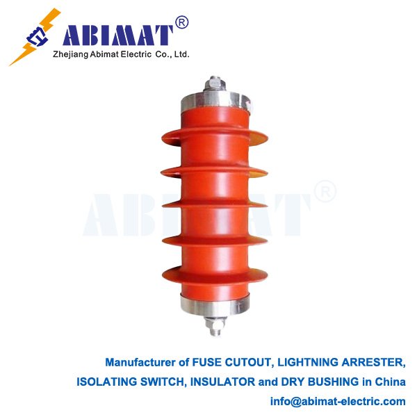
      Abimat modern distribution arresters have some key traits. They have a strong metal-oxide part. This part soaks up energy well and reacts fast too. The arrester is made to be sealed. It uses gaskets, and it’s fully sealed to keep air out. This stops moisture from getting inside—moisture often makes arresters stop working. Old arresters used gap-type technology. Modern ones are different. They have polymeric covers. They’re light, hard to break, and work better. You don’t need series gaps for them.

      Where you place the arresters is really important. You install them between the phase and the earth. Try to put them as close as possible to the equipment they protect. This keeps the impedance of the connecting wires low. It also makes sure the equipment is as safe as it can be. Distribution arresters hold high voltages down to a safe level reliably. This stops insulation from breaking. It also cuts down on system outages. And it makes the whole distribution network more reliable. It even makes the network last longer. So distribution arresters are a must-have. They help keep the power infrastructure strong and efficient.

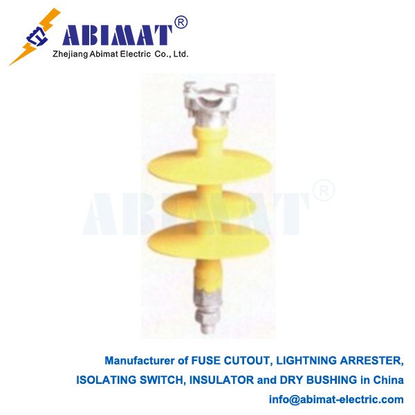
  • Composite Pin Insulators: Enhancing Distribution Network Reliability

    Composite Pin Insulators: Enhancing Distribution Network Reliability

    Composite Pin Insulators: Enhancing Distribution Network Reliability

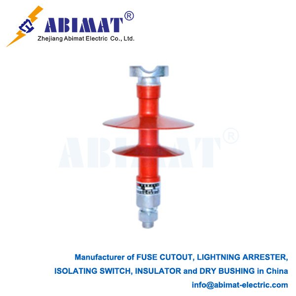
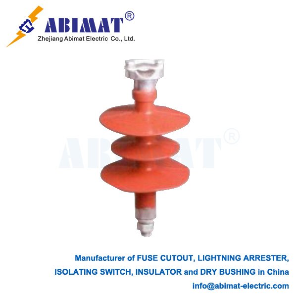
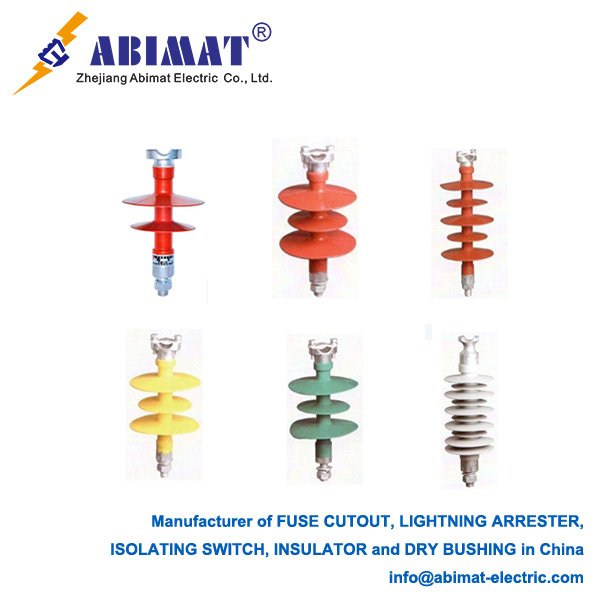
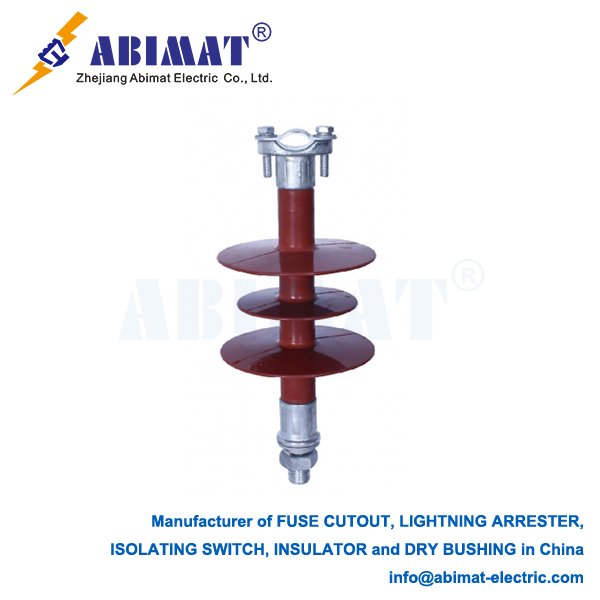
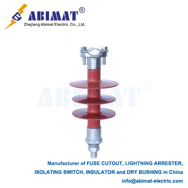
    Composite pin insulators have become the preferred choice over traditional porcelain and glass types for medium-voltage overhead distribution lines, typically operating at 11kV to 33kV and increasingly at 66kV. Their advanced material design delivers superior performance, safety, and longevity in demanding environments.

    Construction Principles

    Three essential components define these insulators:
      I. High-Strength Core: A tensioned fiberglass rod, epoxy-impregnated for stability, provides exceptional mechanical strength to withstand conductor loads, wind, and ice.
      II. Polymeric Weathersheds: Silicone rubber (typically High-Temperature Vulcanizing – HTV or Liquid Silicone Rubber – LSR) forms the outer housing and sheds. This material offers outstanding hydrophobicity, UV resistance, and protection against surface tracking and erosion.
      III. Metal End Fittings: Galvanized steel or ductile iron fittings (socket or tongue style) are permanently secured to the core ends via crimping or compression. These provide robust connection points to the pole crossarm and conductor.

    Operational Advantages

    Composite pin insulators offer significant benefits:

       Reduced Weight: Up to 80% lighter than porcelain equivalents, easing handling, installation, and reducing structural demands on poles.

       Superior Contamination Performance: Silicone rubber’s inherent hydrophobicity prevents water film formation, drastically reducing leakage current and flashover risk in polluted, coastal, or humid conditions.

       Enhanced Vandalism and Impact Resistance: The tough, flexible polymer housing resists damage from gunshots, impacts, and flying debris without shattering – a critical safety improvement over brittle ceramics.

       Excellent Pollution Handling: Optimized aerodynamic shed profiles, combined with hydrophobicity transfer, effectively manage contamination build-up, minimizing maintenance needs.

       Weather Durability: High-quality silicone formulations resist degradation from intense UV exposure, ozone, and extreme temperature cycling far better than older materials.

       Inherent Safety: Failure modes involve gradual housing degradation rather than explosive shattering, significantly reducing hazards for field personnel.

    Critical Design and Performance Factors

       Creepage Distance: Shed profiles are engineered to provide optimal creepage paths for specific pollution severity levels (per IEC 60815), often exceeding the protection offered by similarly rated porcelain units.

       Moisture Sealing: Precision sealing at the core/fitting/housing interfaces (using silicone gels/gaskets) is paramount to prevent moisture ingress and potential core brittle fracture (CBF).

       Core-End Fitting Interface: The mechanical connection between the fiberglass core and metal fitting is a critical engineered joint, designed for long-term integrity under constant mechanical load and environmental stress.

       Flame Retardancy: Quality composite insulators meet stringent self-extinguishing standards.

    Primary Applications

    Composite pin insulators excel in:

       Overhead distribution lines (11kV, 22kV, 33kV, 66kV)

       Service drops and tap connections

       High-pollution zones (industrial areas, coastlines, road salt corridors)

       Regions experiencing icing or heavy wet snow

       Locations requiring high vandalism resistance

       Projects where reduced weight offers logistical or structural advantages

    Quality Assurance

    Compliance with international standards (e.g., IEC 61952) ensures rigorous validation through:

       Mechanical load tests (tensile, compressive, torsion)

       Electrical performance tests (dry/wet power frequency withstand, lightning impulse withstand)

       Environmental tests (thermal mechanical cycling, water diffusion)

       Material tests (tracking/erosion resistance, hardness, tear strength)

       Long-term ageing assessments

    Conclusion

    Abimat composite pin insulators represent a significant advancement in distribution network technology. Their superior performance in harsh conditions, combined with substantial operational benefits like reduced weight, enhanced safety, and lower lifetime maintenance costs, drives their widespread adoption. Continuous improvements in materials and manufacturing further solidify their role as essential components for resilient and efficient power delivery. Selecting insulators based on specific application requirements and sourcing from manufacturers adhering to stringent quality standards is vital for maximizing their long-term reliability and value.

  • Zinc Oxide Gapless Arresters: Advanced Overvoltage Protection

    Zinc Oxide Gapless Arresters: Advanced Overvoltage Protection

    Zinc Oxide Gapless Arresters: Advanced Overvoltage Protection

    Zinc Oxide (ZnO) gapless surge arresters represent the pinnacle of modern overvoltage protection technology for electrical power systems. Replacing older gapped designs, they provide superior, reliable defense against damaging voltage surges originating from lightning strikes, switching operations, and faults.

    The Gapless Revolution

    Traditional arresters, primarily silicon carbide (SiC) types, relied on spark gaps in series with resistive blocks. These gaps introduced inherent limitations: susceptibility to contamination altering sparkover voltage, a finite time delay to conduct (risking inadequate protection for very fast transients), and the need to interrupt potentially large power follow currents after surge discharge. The development of ZnO varistor ceramics in the 1970s enabled the elimination of these gaps, creating the “gapless” arrester.

    Core Technology: The ZnO Varistor

    The arrester’s heart is a column of ZnO varistor blocks. These bulk ceramics consist primarily of zinc oxide grains (>90%) doped with small amounts of other metal oxides (e.g., Bi₂O₃, Sb₂O₃, MnO, CoO). Critically, this creates a microstructure where highly conductive ZnO grains are separated by thin, highly resistive intergranular layers. These grain boundaries function as millions of microscopic “back-to-back Zener diodes” within the material.

    Exceptional Nonlinear Voltage-Current Characteristic

    This unique structure grants ZnO its defining property: an extremely nonlinear voltage-current (V-I) relationship:
      I. High Impedance at Normal Voltage: Under continuous system operating voltage, the arrester exhibits very high resistance (megohms), drawing only microamperes of leakage current, posing negligible load.
      II. Sharp Conduction Onset: When an overvoltage exceeds a critical threshold (the reference voltage), the grain boundaries rapidly break down.
      III. Effective Voltage Clamping: Resistance drops dramatically (orders of magnitude in nanoseconds), diverting massive surge current (kA) harmlessly to earth. Crucially, the voltage across the arrester clamps to a predictable, limited level – the protective level.
      IV. Instantaneous Recovery: Once the surge passes and voltage falls below the threshold, the high resistance is restored instantly. No power follow current exists to interrupt, eliminating a major drawback of gapped arresters.

    Key Advantages of the Gapless Design

      I. Elimination of Spark Gaps: Removes issues like sparkover delay, sensitivity to contamination/pressure, and the need for follow current interruption mechanisms. This significantly enhances reliability and simplifies design.
      II. Superior Protective Level: The sharp knee point and lower clamping voltage provide a larger protection margin for sensitive equipment (transformers,  generators).
      III. Ultra-Fast Response: Responds virtually instantaneously (nanoseconds) to steep-fronted surges and Very Fast Transient Overvoltages (VFTOs), crucial for modern switchgear and GIS.
      IV. High Energy Handling: ZnO varistors absorb immense surge energy densities, enabling compact designs even for EHV/UHV applications.
      V. Stable Performance: Well-manufactured ZnO blocks maintain stable characteristics over long operational lifetimes under normal conditions. Monitoring leakage current offers valuable diagnostic insight into aging or contamination.
      VI. DC System Compatibility: The absence of gaps makes ZnO arresters uniquely suited for HVDC transmission systems where follow current interruption is impossible.

    Critical Applications

    ZnO gapless arresters are ubiquitous:

       Substation Protection: Safeguarding transformers, circuit breakers, busbars, and switchgear.

       Transmission & Distribution Lines: Protecting overhead lines and cable systems.

       Rotating Machinery: Shielding generators and large motors.

       Industrial & Renewables: Securing sensitive process controls, wind turbines, and solar inverters.

       HVDC Systems: Essential for converter stations and DC lines.

    Conclusion

    Zinc Oxide gapless surge arresters are fundamental to modern electrical system resilience. Their core technology – the highly nonlinear ZnO varistor – provides fast, reliable, and predictable overvoltage clamping without the limitations of spark gaps. Offering superior protection levels, rapid response, high energy absorption, inherent stability, and DC compatibility, ZnO gapless arresters are indispensable for safeguarding critical infrastructure, ensuring operational continuity, and enabling the advancement of complex power grids. Continuous material and design improvements further solidify their role as the premier overvoltage protection solution.

  • Air Break Disconnect Switches: Essential Isolating Devices in Power Systems

    Air Break Disconnect Switches: Essential Isolating Devices in Power Systems

    Air Disconnect Switches: Critical Components for System Safety & Flexibility

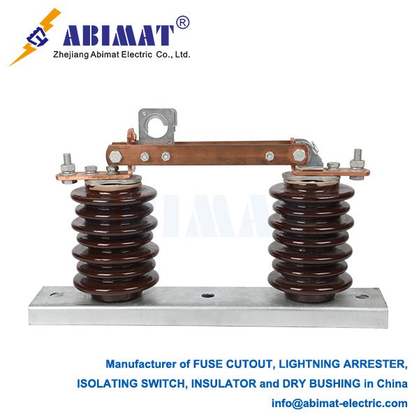
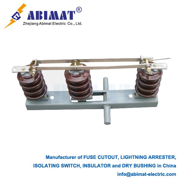
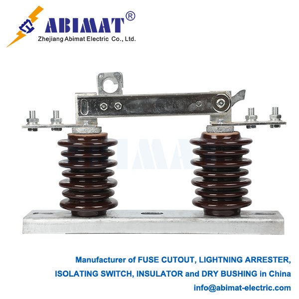
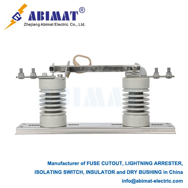
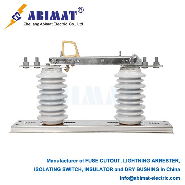
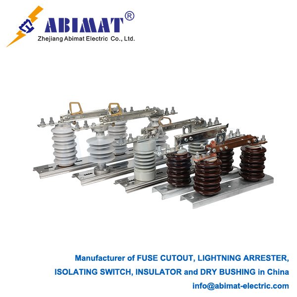
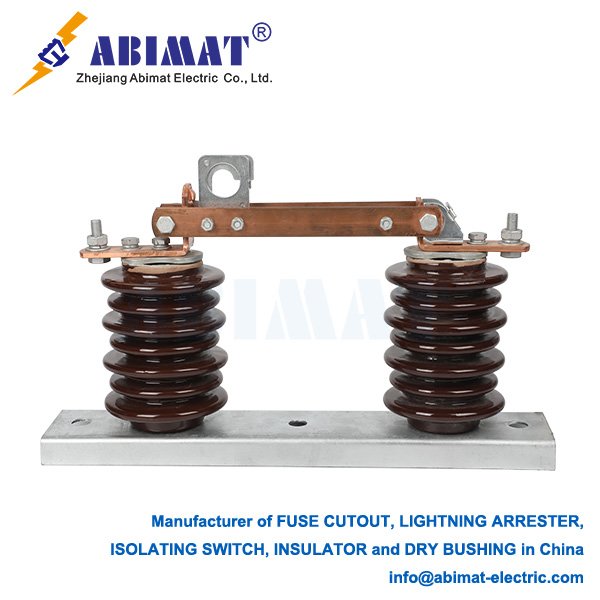
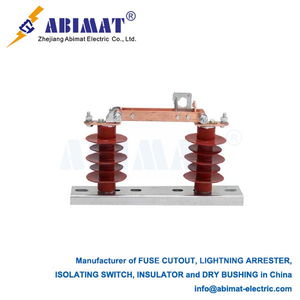
    While often grouped with circuit breakers, Air Disconnect Switches (ADS) serve distinct, vital roles in electrical power infrastructure. Their core purpose is to establish a safe, visible, and reliable physical air gap in de-energized circuits. This isolation is fundamental for personnel safety during maintenance (“Lockout/Tagout”), equipment servicing, and system reconfiguration. Unlike breakers, ADS lack any significant current interruption capability and operate solely on the principle of physical contact separation using ambient air as insulation.

    Core Functionality & Operational Context:

      I. Isolation Assurance: The primary function is unambiguous isolation. When opened, the physical air gap provides visual confirmation that a circuit section is disconnected from its voltage source, a non-negotiable safety requirement per standards like IEEE C37.20.2 and IEC 62271-102.
      II. No-Load Operation: ADS are strictly make-or-break devices for unloaded circuits only. Opening under load current creates a destructive, sustained arc. Operation must always follow de-energization by an upstream interrupting device (e.g., circuit breaker). Interlocks often enforce this sequence.
      III. Voltage Withstand & Dielectric Integrity: In the open position, the switch must reliably withstand system operating voltage and specified transient overvoltages (BIL – Basic Impulse Level). The design of the air gap, arcing horns (to control and extinguish small incidental arcs), and insulating supports (porcelain or polymer) are critical.
      IV. Earthing Integration: ADS are frequently paired with integrated or separate Earthing Switches (Grounding Switches). Once isolated, the earthing switch provides a safe, visible ground connection to discharge capacitive energy and ensure the isolated section remains at earth potential during work.

    Key Design Variations & Selection Criteria:

       Voltage Class: Ranging from Medium Voltage (MV, e.g., 5kV-38kV) to Extra High Voltage (EHV, e.g., 145kV-765kV), design complexity increases significantly with voltage. EHV switches often feature multiple breaks per phase.

       Mounting Style:

           Dead Tank: The switch enclosure (tank) is at earth potential. Common for higher voltages and GIS (Gas-Insulated Switchgear) bushings.

           Live Tank: The interrupting chamber is at line potential, supported by an insulated column. Common for outdoor substations.

       Contact Movement:

           Vertical Break: Contacts separate vertically. Offers good pollution performance (self-cleaning by rain) and compact horizontal footprint.

           Center Break: Contacts rotate horizontally from a central pivot. Often used for lower ratings or indoor applications.

           Pantograph (Semaphore): Uses a folding linkage, providing a high vertical break in a relatively compact design.

       Operation: Manual (via rotating handle and gearbox with visible position indicator), motor-operated (remote control), or occasionally pneumatic/hydraulic. Motor drives are essential for remote operation and interlocking schemes.

       Enclosure: Outdoor switches are exposed to environmental stresses (wind, ice, pollution). Indoor switches are often housed within metal-clad switchgear, providing “dead-front” safety (no exposed live parts when closed).

    Critical Applications Beyond Basic Isolation:

    1. Bus Sectionalizing: Dividing busbars into isolated sections enhances system flexibility, allows partial maintenance without full shutdown, and limits fault impact.
    2. Bypass Operation: Facilitating the isolation and bypass of critical equipment like circuit breakers or transformers for maintenance using transfer bus schemes.

    III.  Capacitor Bank Switching (De-Energized): Isolating capacitor banks after they have been de-energized by a breaker. (Note: Dedicated Load Break Switches or breakers handle energization/de-energization due to capacitive currents).

    1. Generator Isolation: Providing the main point of isolation between a generator and the step-up transformer or grid connection for safe maintenance.
    2. Temporary Feed Routing: Enabling safe reconfiguration of distribution feeders for repair or load transfer.

    Essential Safety & Operational Considerations:

       Strict Adherence to Procedures: Operating ADS under load is extremely hazardous. Rigorous switching procedures and interlocking are mandatory.

       Visible Verification: The open air gap is the primary safety indicator. Auxiliary contacts for remote signaling supplement but never replace visual verification for safety grounding.

       Mechanical Endurance: Designed for infrequent operation (typically hundreds to thousands of cycles), but must remain reliable over decades, often in harsh environments. Regular inspection and lubrication are key.

       Corona & Radio Interference Voltage (RIV): Critical design factors at HV/EHV to prevent excessive discharge and electromagnetic interference.

    Conclusion

    Abimat Air Disconnect Switches are indispensable safety devices, not current interrupters. Their value lies in providing a definitive physical break and visible isolation point. Proper selection (voltage, mounting, operation type), integration with earthing switches, strict adherence to operational limits (no-load switching only), and rigorous safety procedures are paramount. They underpin system flexibility for maintenance and reconfiguration, forming a foundational layer of safety and operational control in power networks worldwide.

  • Essential Protection: The Role of 66kV Surge Arresters

    Essential Protection: The Role of 66kV Surge Arresters

    Essential Protection: The Role of 66kV Surge Arresters

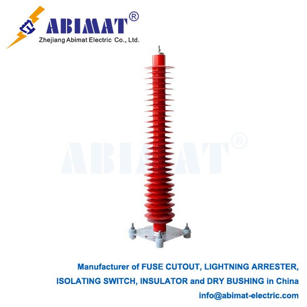
    Within electrical power systems operating at 66kV, surge arresters are critical protective devices. Installed at substations, along transmission lines, and near sensitive equipment, their primary function is safeguarding transformers, switchgear, circuit breakers, and other vital assets from destructive voltage surges.

    The Nature of Voltage Surges

    Voltage surges are transient overvoltages, typically lasting microseconds, originating from:

    1.  Lightning: Direct strikes to lines or structures, or induced voltages from nearby strikes.
    2.  Switching Operations: Energizing or de-energizing lines, capacitor banks, or transformers; interrupting fault currents.
    3.  System Faults: Ground faults or phase-to-phase faults.

    These events can generate voltages significantly exceeding the system’s nominal 66kV (RMS phase-to-phase) and the equipment’s Basic Insulation Level (BIL). Without mitigation, such surges cause insulation failure, equipment damage, and costly outages.

    Core Technology: Metal-Oxide Varistors (MOV)

    Modern 66kV surge arresters rely primarily on Zinc Oxide (ZnO) Metal-Oxide Varistors. Under normal operating voltage (typically 40-45kV RMS line-to-ground), the MOV blocks exhibit extremely high resistance, conducting only minimal leakage current. When a surge exceeds the arrester’s triggering voltage, the MOV’s resistance drops dramatically within nanoseconds. This creates a low-impedance path to earth, safely diverting the surge current around the protected equipment. Once the surge passes, the arrester rapidly returns to its high-resistance state, restoring normal operation.

    Key Technical Specifications

    Selecting and applying 66kV arresters requires careful attention to these parameters:

       Rated Voltage (Ur): The maximum permissible continuous power-frequency voltage (RMS) the arrester can withstand during specified temporary overvoltage (TOV) conditions. Common Ur values for 66kV systems are 60kV or 66kV.

       Continuous Operating Voltage (Uc): The maximum permissible continuous power-frequency voltage (RMS) across the arrester terminals under steady-state conditions. This must exceed the system’s maximum continuous line-to-ground voltage.

       Nominal Discharge Current (In): The peak value of the standard 8/20 µs current wave used for classifying the arrester’s duty class (e.g., 10kA, 20kA). Higher ratings indicate greater energy handling capacity.

       Residual Voltage (Ur): The peak voltage measured across the arrester terminals when discharging the nominal discharge current (In). This value must be lower than the BIL of the protected equipment. Lower residual voltage indicates superior protection.

       Pressure Relief Class: Ensures the arrester safely vents internal gases during catastrophic failure without violent rupture.

       Creepage Distance: Essential for maintaining performance in polluted environments.

    Application and Installation

    Robustly constructed with porcelain or polymer housings for outdoor durability, 66kV arresters are typically installed:

       Directly adjacent to transformers (on the line side).

       At substation line entrances and on critical busbars.

       On overhead lines susceptible to lightning.

       At transitions between overhead lines and underground cables.

    A low-impedance connection to a well-designed grounding system is essential for effective surge energy dissipation.

    Maintenance Considerations

    While the Abimat modern arresters are largely maintenance-free, periodic visual inspections for physical damage, contamination, or surface tracking are prudent. Leakage current monitoring devices can provide early indications of potential MOV degradation or moisture ingress.

  • Disconnect Switches: Critical Safety Infrastructure in Substations

    Disconnect Switches: Critical Safety Infrastructure in Substations

    Disconnect Switches: Critical Safety Infrastructure in Substations

    Disconnect switches (isolators) serve as indispensable components within electrical substations, providing essential safety isolation and operational flexibility. Unlike circuit breakers, these devices are not designed to interrupt load or fault currents. Their fundamental purpose is to establish a visible, physical air gap in de-energized circuits, ensuring safe equipment isolation for maintenance, testing, or system reconfiguration.  

    Primary Functions

      I. Safety Assurance: Creates unambiguous isolation points for work on transformers, circuit breakers, or bus sections. The visible gap verifies de-energization before grounding equipment.
      II. System Configuration: Enables power flow management by:
        – Isolating feeders or bus sections
        – Transferring loads between busbars
        – Bypassing equipment
        – Connecting/disconnecting transmission lines
      III. Equipment De-energization: Safely isolates downstream equipment after circuit breaker operation.

    Common Substation Types

    – Vertical-Break (66kV+): Rotating blades create vertical air gaps; standard for high-voltage outdoor installations.  

    – Center-Break: Horizontally rotating blades; typical for lower-voltage applications.  

    – Double-Break: Semaphore-style blades creating two series gaps; enhanced dielectric strength.  

    – Pantograph: Scissor mechanism for space-constrained bus connections.  

    – In-Line: May incorporate limited load-breaking capability or fuse integration.

    Critical Design Parameters

    Selection requires rigorous evaluation of:  

    – Electrical Ratings: Voltage class, continuous current, short-time withstand (kA/s), peak withstand current  

    – Dielectric Performance: Power frequency/impulse withstand voltage across open gap  

    – Environmental Resilience: Creepage distance (IEC 60815 pollution levels), ice/wind loading  

    – Mechanical Endurance: Minimum 1,000 operation cycles  

    – Actuation: Manual (lever/crank) or motorized operation for remote control  

    Operational Imperatives

    – Visual Verification: Field personnel must physically confirm open-gap position before accessing equipment.  

    – Interlocking Systems: Prevent hazardous operations through:  

      – Mechanical key transfers blocking switch operation under load  

      – Electrical interlocks preventing closure on grounded circuits  

      – SCADA-controlled sequencing for automated substations  

    – Arc Management: Engineered to safely interrupt capacitive currents (e.g., unloaded bus charging current) using blow-open hooks or arc horns.  

    – Integrated Grounding: Paired with earthing switches for safe discharge of isolated sections.  

    Substation Applications

    – Transformer/reactor isolation  

    – Circuit breaker maintenance bypass  

    – Busbar sectionalization  

    – Feeder connection/disconnection  

    – Test point establishment  

    Compliance and Maintenance

    Governed by IEC 62271-102/ANSI C37.32 standards covering design, testing, and commissioning. Critical maintenance includes:  

    – Infrared scanning for contact overheating  

    – Visual inspection of blade alignment/contact erosion  

    – Lubrication of rotating mechanisms  

    – Interlock function verification  

    – Pollution monitoring in coastal/industrial areas  

    Conclusion

    Abimat Disconnect switches form the backbone of substation safety protocols. Their ability to establish reliable visible isolation enables critical maintenance, protects personnel, and facilitates system reconfiguration. Proper selection based on electrical/mechanical requirements, integration of failsafe interlocks, and disciplined maintenance directly impact substation reliability. As power networks evolve, these fundamental devices remain vital for secure, resilient grid operations—where engineered safety solutions prevent human error and ensure operational continuity.  

  • Composite Insulator Materials: Performance Through Design

    Composite Insulator Materials: Performance Through Design

    Composite Insulator Materials: Performance Through Design

    Composite (polymeric) insulators are essential components in modern high-voltage (HV) and extra-high-voltage (EHV) transmission and distribution systems. Their superior performance stems from the strategic combination of specialized materials:

    I. Load-Bearing Core:

           Material: Tensioned E-glass or R-glass fibers embedded in a thermosetting resin matrix (epoxy or vinyl ester).

           Function: Provides high tensile strength and mechanical support. The resin protects fibers from moisture and chemicals, ensuring long-term integrity and a non-brittle failure mode.

           Key Advantage: High strength-to-weight ratio, excellent fatigue resistance.

    II. Weathershed Housing:

           Material: High-Temperature Vulcanized Silicone Rubber (HTV SIR) is predominant. Ethylene Propylene Diene Monomer (EPDM) is less common.

           Function: Provides primary electrical insulation, controls electric field distribution, and protects the core. Shed profiles maximize creepage distance.

           Critical Properties:

               Hydrophobicity: Intrinsic water repellency causes moisture to bead up, significantly suppressing leakage currents and preventing uniform wet pollution layers.

               Hydrophobicity Recovery: SIR transfers hydrophobic properties to pollutants and recovers hydrophobicity after wetting or surface discharge – a vital self-cleaning mechanism.

               Tracking/Erosion Resistance: Exceptional ability to resist formation of permanent conductive paths under electrical stress and pollution.

               UV/Ozone Resistance: Superior long-term stability against environmental degradation.

    III. End Fittings:

           Material: Galvanized ductile iron or forged steel.

           Function: Connect the insulator mechanically to structures and conductors, transmitting loads to the core.

    IV. Critical Interface:

           Material/Process: Specialized adhesives/coupling agents combined with precision crimping/swaging.

           Function: Creates a permanent, water-tight, high-strength bond between the fiberglass core and metal end fittings, and between the core and rubber housing. Prevents moisture ingress leading to core degradation (“brittle fracture”).


    Material-Driven Advantages vs. Porcelain/Glass:


       Lightweight: ~70-90% lighter, enabling easier handling, lower transportation/structural costs, and retrofitting on existing lines.

       Superior Pollution Performance: Hydrophobicity and recovery drastically reduce pollution-related flashovers, minimizing maintenance (e.g., washing).

       High Vandalism/Impact Resistance: Flexible rubber housing resists damage from gunfire or flying debris; core doesn’t shatter.

       Enhanced Safety: Explosion-proof under internal faults (no shattering).

       Excellent Creepage Efficiency: Optimized shed profiles offer more effective creepage per unit length.

       Reduced Maintenance: Self-cleaning properties significantly lower lifetime costs in polluted areas.

    Applications: Dominant in modern:

       Long-Term Aging: Continuous monitoring of material degradation under electrical, mechanical, and environmental stress.

       Critical Quality Control: Rigorous manufacturing control, especially for core impregnation, rubber vulcanization, and end-fitting interfaces, is paramount for reliability.

       Specialized Inspection: Techniques like infrared thermography or UV corona cameras supplement visual checks.

    Conclusion

    Composite insulator materials, particularly the synergistic fiberglass core and silicone rubber housing, deliver unparalleled advantages in weight, pollution performance, safety, and durability. Their engineered material properties make them the preferred solution for reliable, efficient, and resilient power networks globally, especially in harsh environments.

  • Cut-Out Fuse: Core Functions in Distribution Systems

    Cut-Out Fuse: Core Functions in Distribution Systems

    Fuse Cutout Covers: Core Functions in Distribution Systems

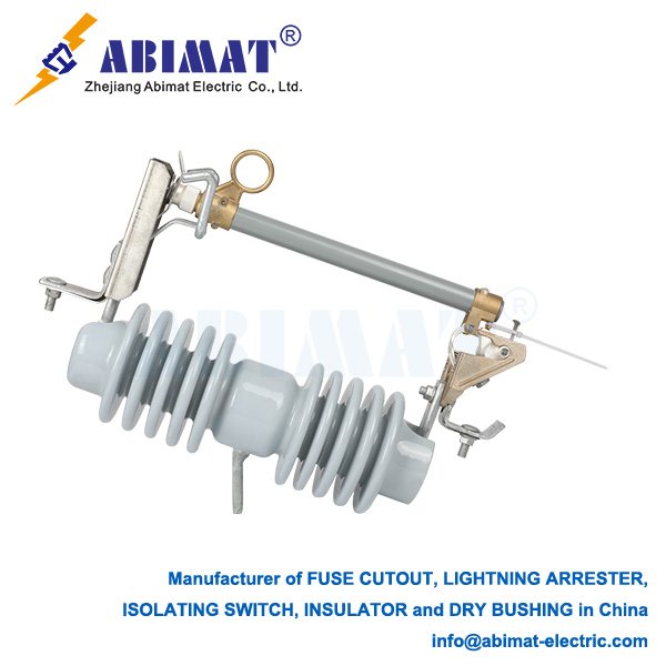
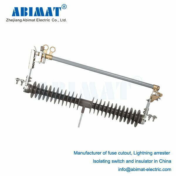
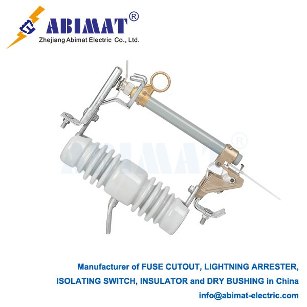
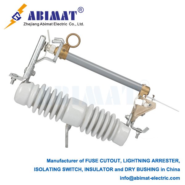
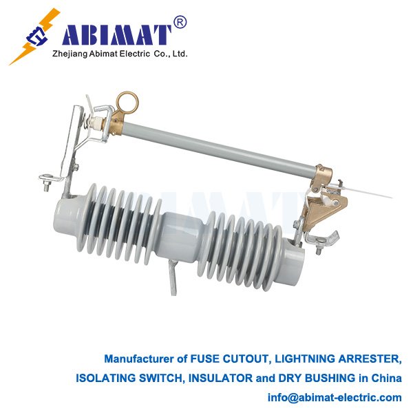
    The Fuse cutout is a vital, self-contained protective device predominantly used on overhead medium-voltage (MV) distribution networks (e.g., 11kV, 33kV). Its primary fungsi (functions) are overcurrent protection and safe, visible isolation, ensuring system safety, reliability, and maintainability.

    I.Overcurrent and Fault Protection:

       Sacrificial Element: The core component is a precisely calibrated fuse link within a removable carrier. Under normal load current, it remains intact.

       Abnormal Current Response:

           Sustained Overloads: Current exceeding the fuse’s continuous rating for a sufficient duration causes the link to melt via Joule heating, protecting downstream equipment (e.g., transformers, cables) from thermal damage.

           Short Circuits: Extremely high fault currents cause near-instantaneous melting of the fuse link.

       Selective Coordination: Cut-outs are selected based on time-current characteristics (TCC) to coordinate with upstream devices (reclosers, breakers) and downstream fuses. This ensures the device closest to the fault operates first, minimizing outage impact and maintaining supply to healthy sections.

    II.Visible Open Isolation:

       Drop-Out Mechanism: Following fuse operation, an internal release mechanism allows the fuse carrier (or “door”) to pivot downward under gravity.

       Clear Visual Indication: This dropped-open position provides linemen with unambiguous, immediate visual confirmation that:

           The circuit downstream is electrically isolated from the live upstream section.

           A fault or persistent overload has occurred on the protected circuit segment.

           It is safe (after proper de-energization verification and grounding procedures) to approach the downstream equipment for repair or fuse replacement.

       Lockout Capability: Many designs allow locking the carrier in the open position during maintenance (Lockout/Tagout – LOTO).

    HGRW1-40.5 35kV windproof fuse cutout - ABIMAT ELECTRIC

    Operational Principle & Key Features:

       Interruption: The fuse link melts within a sealed tube, often filled with arc-quenching sand (silica). The sand rapidly cools and de-ionizes the plasma arc, safely interrupting the current.

       Robust Enclosure: Housed within durable, weatherproof insulators (porcelain or polymer), designed for harsh outdoor environments (UV, rain, pollution, temperature swings).

       Ease of Operation: Allows linemen using insulated hot sticks to safely open (unload only) or close the cut-out, and easily replace the fuse carrier once the fault is cleared.

       Interrupting Rating: Rated to safely clear fault currents up to a specified maximum value (kA) without rupture.

    Primary Applications:

      I. Distribution Transformer Protection: The most common use. Installed on the primary (HV) side of pole-mounted or pad-mounted transformers, protecting them from internal faults and secondary-side faults.
      II. Lateral Feeder Protection: Sectionalizing distribution feeders, isolating faults on branch lines (laterals) to minimize disruptions on the main feeder.
      III. Capacitor Bank Protection: Isolating faulty units in pole-mounted capacitor banks.
      IV. Service Entrance Protection: For larger overhead commercial or industrial services.

    Critical Safety & Operational Aspects:

       NO Load Switching: Cut-outs are not designed to interrupt normal load currents. They must only be operated (opened/closed) when the circuit is de-energized or carrying negligible current.

       Visual Verification: The dropped carrier is the primary safety indicator; remote status signals are supplementary.

       Correct Rating: Using the manufacturer-specified fuse link rating is essential for proper protection and coordination.

       Regular Inspection: Essential to check for insulator damage, corrosion, contamination, and ensure smooth carrier operation.

    Conclusion

    The Abimat Fuse Cutout fulfills two indispensable fungsi in MV overhead networks: reliable overcurrent protection to safeguard equipment and limit fault impact, and fail-safe visible isolation enabling safe maintenance and rapid restoration. Its simplicity, durability, clear visual status indication, and ease of fuse replacement make it a cornerstone of distribution system safety, reliability, and operational efficiency.

    15kV 300A DISCONNECT BLADE FUSE CUTOUT abimat electric 2
  • 150 kV Disconnecting Switches: Critical Components for High-Voltage Safety

    150 kV Disconnecting Switches: Critical Components for High-Voltage Safety

    150 kV Disconnecting Switches: Critical Components for High-Voltage Safety

    A 150 kV disconnecting switch (isolation switch) serves as a fundamental safety device in high-voltage electrical networks. Its primary function is to establish a visible, physical air gap in de-energized circuits, ensuring safe isolation during maintenance or repair operations. Crucially, it lacks arc-interruption capability and must operate only after upstream circuit breakers have cleared the circuit of load current.

    Design and Operational Principles:

       Visible Isolation: Provides unambiguous visual confirmation of circuit disconnection—a critical safety requirement exceeding purely electrical indicators.

       Contact Configuration: Employs double-break contacts per phase, creating two series air gaps. This design significantly enhances dielectric strength compared to single-break types, improving reliability at 150 kV.

       Actuation Mechanism: Utilizes robust motorized drives (typically brushless DC motors) with closed-loop position and speed control. Precision control prevents unsafe partial engagement and ensures consistent operation across environmental conditions.

       Insulation System: Relies on high-strength polymer composite or porcelain insulators, specifically rated for 150 kV operation, to withstand system voltage and transient overvoltages.


    Key Safety and Performance Features:

       I. Electrical Integrity: Engineered to withstand standard power frequency withstand voltages (e.g., 275 kV AC) and lightning impulse withstand voltages (e.g., 650 kV BIL) as per IEC 62271-102. Maintains insulation integrity during transient recovery voltage (TRV) events.
      II. Interlocking Systems: Integrates mandatory mechanical and/or electrical interlocks with associated circuit breakers. This prevents operation under load—a critical safeguard against catastrophic failure.
      III. Environmental Protection: Features corrosion-resistant alloys for mechanical components and hydrophobic silicone rubber coatings on composite insulators. This mitigates performance degradation from pollution, salt fog, or industrial contaminants.
      IV. Mechanical Endurance: Designed for a minimum mechanical life of 10,000 operations under rated conditions, ensuring long-term reliability.

    Applications and Technological Integration:

       Core Applications: Essential in substations for isolating transformers, bus sections, feeders, and transmission lines. Widely used in renewable generation facilities (e.g., solar farms, wind parks) for DC array isolation and grid connection points.

       Advanced Control & Monitoring: Modern switches incorporate digital signal processor (DSP)-based control systems. These provide real-time monitoring of blade position, motor torque, and operating speed, enabling predictive maintenance and fault detection (e.g., jamming, incomplete closure).

       Innovation Trends: Development focuses on integrating IoT sensors for continuous condition monitoring (contact resistance, insulator pollution levels) and exploring hybrid designs incorporating solid-state elements for niche arc-less interruption applications.

    Standards and Certification:

    Design, testing, and certification strictly adhere to international standards:

       IEC 62271-102: Governs requirements, dielectric testing, mechanical endurance, and temperature rise tests.

       ANSI/IEEE C37.32: Specifies American standards for ratings, construction, and testing.

       Independent certification by bodies like KEMA or UL validates compliance and safety performance.

    Critical Operational Protocol:

    Disconnecting switches function solely as isolation devices. Strict operational sequences are mandatory:
      I. De-energize the circuit via the upstream circuit breaker.
      II. Verify absence of voltage.
      III. Operate the disconnecting switch to open position.
      IV. Apply lockout/tagout (LOTO) safety devices.

  • 150 kV Disconnecting Switches: Critical Components for High-Voltage Safety

    150 kV Disconnecting Switches: Critical Components for High-Voltage Safety

    Fuse Cutout Switches: Essential Protection Devices in Medium-Voltage Distribution Systems

    Fuse cutout switches serve as critical protection and isolation components in overhead distribution networks, typically operating at 15 kV to 38 kV. These devices integrate three fundamental functions: overcurrent protection through fuse operation, visible circuit isolation, and manual switching capability for maintenance operations.

    Design and Operational Principles:

       Fuse Protection Mechanism: Contains a precisely calibrated fuse element (commonly tin-silver alloy) designed to melt under sustained fault currents. This action disconnects faulted sections from the network.

       Visible Disconnection: Upon fuse operation, the pivoting fuse holder assembly drops to a downward position, providing unambiguous visual confirmation of the interrupted circuit.

       Isolation Function: Linemen manually operate the switch using insulated hot sticks to establish a visible air gap for maintenance safety, complying with lockout/tagout (LOTO) requirements.

    Key Technical Features:

      I. Expulsion Fuse Tube: Fabricated from fiberglass-reinforced polymer (FRP), this component channels arc-generated gases downward to extinguish the arc within 0.5–2 cycles of fault initiation.
      II. Sealed Insulation System: Features hydrophobic cycloaliphatic epoxy or polymer housings with minimum creepage distances of 25 mm/kV. Silicone rubber seals prevent moisture penetration.
      III. Dielectric Performance: Designed with Basic Impulse Level (BIL) ratings from 95 kV to 150 kV to withstand lightning surges and switching transients.
      IV. Current-Limiting Action: Fast-acting fuse links (T-speed characteristic: 0.01–10 seconds) restrict prospective fault currents below 10 kA, protecting downstream equipment.

    Performance Specifications:

    – Rated Voltage: 15–38 kV (IEC 62271-111, IEEE C37.41)

    – Maximum Interrupting Current: 8–16 kA RMS symmetrical

    – Mechanical Endurance: Minimum 200 full-load operations (IEC 60282-1)

    – Withstand Voltage: 50 kV power frequency for 1 minute (dry conditions)

    Primary Applications:

       Protection for pole-mounted distribution transformers

       Sectionalizing points on overhead feeders

       Switching for capacitor banks

       Interconnection points for distributed renewable resources

    Operational Advantages:

      I. Rated Fault Clearing: Interrupts faults within two cycles, minimizing thermal damage to system components.
      II. Positive Disconnection: Gravity-assisted drop-out mechanism ensures physical isolation independent of operator action.
      III. Contained Arcing: The expulsion design prevents external arcing, maintaining incident energy below 2 cal/cm² at 38 kV.
      IV. Maintenance Safety: Visible open gap enables compliance with OSHA LOTO procedures.

    Standards Compliance and Maintenance:

       Dielectric Testing: Includes separate wet and dry power frequency tests per IEC 62271-1

       Coordination Requirements: Fuse time-current characteristics must coordinate with upstream/downstream devices per IEEE 242 guidelines

       Field Maintenance: Requires annual infrared inspections (investigate >10°C temperature differentials) and pollution monitoring (cleaning threshold: 0.1 mg/cm² ESDD)

    Technical Evolution:

       Smart Devices: Incorporate current sensors with LoRaWAN or NB-IoT transmitters for fault location identification

       Advanced Materials: Silicone rubber composite insulators replacing porcelain for seismic resistance and vandalism protection

       Environmental Adaptation: UV-stabilized polymer formulations for extended service in ambient temperatures to 60°C

    Conclusion

    Abimat fuse cutout switches remain fundamental components for distribution system protection due to their electromechanical reliability. Proper selection of speed classes (K/T/S) and adherence to IEC/IEEE standards ensure effective coordination and personnel safety. Integration of monitoring capabilities continues to enhance their role in modern grid architectures while maintaining the fail-safe operation essential for field safety.