Author: Zhou

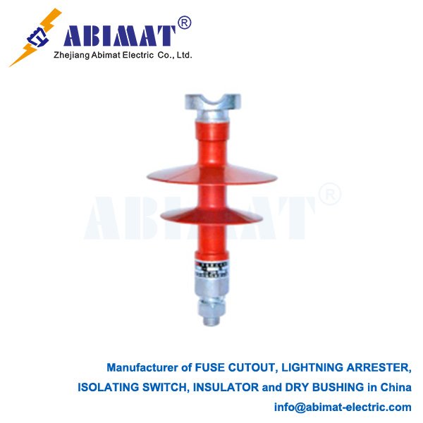
  • Technical Specification: 9kV / 5kA Surge Protective Devices

    Technical Specification: 9kV / 5kA Surge Protective Devices

    Technical Specification: 9kV / 5kA Surge Protective Devices

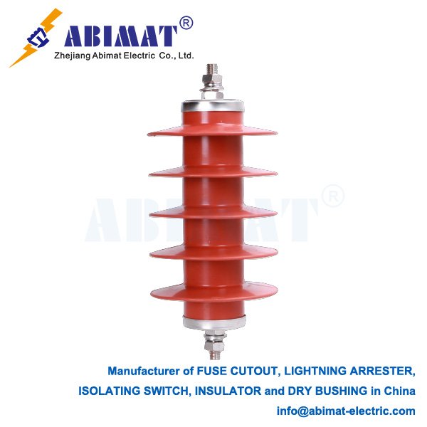
    Surge Protective Devices (SPDs)—often called lightning arresters—are key for protecting electrical systems. They guard against sudden, short-term voltage spikes. These spikes can come from lightning strikes, whether direct or indirect, or from switching equipment on and off. A 9kV / 5kA SPD is built to offer strong protection. It works well in industrial and commercial power distribution systems.

    Key Specifications Explained:

    9kV Maximum Continuous Operating Voltage (MCOV or Uc) is the highest RMS voltage the SPD can handle nonstop across its terminals—like Line-to-Line, Line-to-Neutral, or Line-to-Ground. It won’t break down or turn on by accident. A 9kV MCOV means it works well with systems that have higher normal voltages and can put up with temporary overvoltages (TOVs). You’ll often find it in 480VAC 3-phase systems, where Line-to-Line voltages hit 480V RMS. It also fits in distribution panels after service entrance SPDs and in places where voltages change a lot.  


    5kA Nominal Discharge Current (In) is the peak of a standard 8/20 µs current wave. The SPD must discharge this at least 15 times without getting damaged, following IEC 61643-11. A 5kA In rating shows it can handle medium to high surge currents. These SPDs are Type 2 (Class II) devices. They protect against surges that come from upstream SPDs or start inside a building, dealing with most of the leftover surge energy.

    Technology & Operation:

       The core component in most 9kV/5kA SPDs is the Metal Oxide Varistor (MOV). MOVs show high resistance at normal operating voltages. When voltage exceeds the MOV’s threshold, its resistance drops sharply, creating a low-impedance path to divert surge current safely to ground.


       Engineers design these SPDs for parallel connection across the protected power conductors.

    Critical Performance Parameters:

      Voltage Protection Level (Up) is the highest voltage seen across the SPD’s terminals when it discharges the 5kA In current. A lower Up means better protection for the equipment downstream.  


    MOV-based SPDs have a fast response time—nanoseconds. They clamp down on surges before they can damage equipment.  


    These SPDs also have thermal protection, a fail-safe feature. If an MOV overheats and starts to degrade, built-in thermal disconnectors cut it off from the circuit. This stops fire risks and keeps power flowing, often with a visible sign that something’s wrong.  


    Good SPDs follow standards like IEC 61643-11, UL 1449 5th Edition, or others like them. This ensures their performance and safety are proven.  


    They are mainly put in distribution panels, sub-panels, or critical load panels. You’ll find them in places using 480VAC 3-phase systems or similar higher voltage setups. They protect switchgear, PLCs, motor drives, and other important equipment.

    Summary:

    The Abimat 9kV / 5kA SPD is a key Type 2 protection part for tough electrical environments. It has a 9kV MCOV, which keeps it working steadily—even when line voltages are normal or changing. Its 5kA In rating gives it plenty of capacity. It can repeatedly redirect harmful surge currents, whether from lightning or switching, away from the system.  


    This SPD clamps overvoltages down to a safe level (Up). It also sends surge energy into the ground. Doing this protects industrial and commercial electrical setups, as well as sensitive equipment downstream. When choosing one, you need to think about the system’s specific voltage, the required Up, and the relevant safety standards.

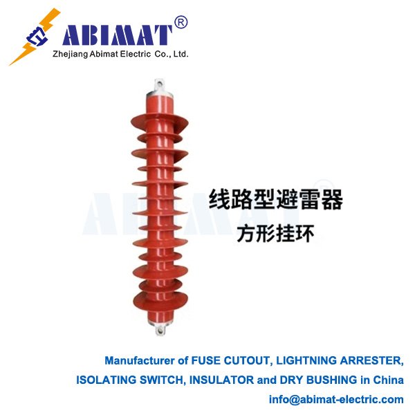
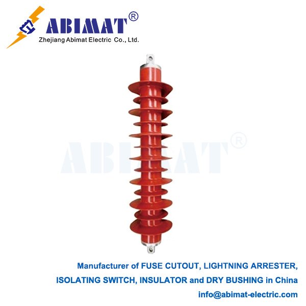
  • Technical Overview of 69 kV Metal Oxide Arresters for Power System Protection

    Technical Overview of 69 kV Metal Oxide Arresters for Power System Protection

    Technical Overview of 69 kV Metal Oxide Arresters for Power System Protection

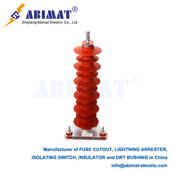
    Lightning arresters are critical for safeguarding medium-voltage power systems (e.g., substations, transmission lines) against transient overvoltages from lightning strikes or switching events. For 69 kV systems, –metal oxide arresters (MOAs)– dominate modern applications due to their superior energy absorption and rapid response characteristics.  

    Core Technical Specifications

    The rated voltage is 69 kV. It matches the system’s operating voltages, keeping things stable during normal use and when faults happen.  


    Continuous operating voltage (Uc) has to be higher than the system’s maximum phase-to-ground voltage. For 69 kV systems, this is usually at least 40.3 kV.  


    Discharge current capacity has a standard 10 kA rating for normal discharge current—this uses an 8/20 μs waveform. It can handle up to 100 kA for bad surges.  


    The protection level limits residual voltage to 2.5 kV or less during surges. This keeps the insulation of downstream equipment in good shape.  


    Leakage current stays below 50 μA at 0.75 times the DC reference voltage. This shows the insulation is healthy and there are few losses from wear.

    Design & Material Advancements

    Modern 69 kV MOAs use zinc oxide (ZnO) valve elements. These elements have a highly nonlinear resistivity, letting them conduct surges passively without needing series gaps.  


    The housing is made of silicone rubber composite, which has several benefits. It is hydrophobic—methyl groups in the material repel moisture, cutting down on flashovers caused by pollution. It is also lightweight: 69 kV units weigh about 50 kg, much lighter than porcelain versions that can hit 260 kg. This makes installation easier.  


    Another plus is pressure relief. Wedge-notched fiberglass tubes and explosion-proof designs help safely release internal arcs when faults happen.

    Performance Validation & Standards

    Strict testing follows GB/T 11032-2018 and IEC 60099-4. One key test is the high-current test: they handle 100 kA lightning impulses (8/20 μs) and 4/10 μs high currents without failing.  


    Residual voltage tests check how well they protect equipment. These tests use 1/10 μs steep waves and 30/60 μs switching surges to measure their effectiveness.  


    Long-term stability is also verified. The temperature coefficient is no more than 0.05% per °C, so they work consistently even when temperatures range from -40°C to +85°C.

    Installation & Field Considerations

    Grounding is important. The ground resistance should be no more than 10 Ω in most cases, or 30 Ω in areas with high resistivity.  


    Connection geometry matters too. Phase and ground leads need to be 1 meter or shorter to keep inductance low. Sharp bends should be avoided.  


    Monitoring is required. Every year, before the monsoon, check for visible damage or sudden increases in leakage current.

    Conclusion

    Abimat 69 kV MOAs offer strong protection against overvoltage. They use advanced ZnO technology and polymer housing to do this. Following standard tests—like those in GB/T 11032—keeps them reliable in both utility and industrial settings.  

    Good grounding and regular maintenance help keep the system strong. Looking ahead, there’s a trend toward adding IoT sensors. These will monitor wear in real time.

  • The Essential Role of Disconnecting Switches in Electrical Systems

    The Essential Role of Disconnecting Switches in Electrical Systems

    The Essential Role of Disconnecting Switches in Electrical Systems

    In electrical systems—from big substations to busy industrial sites—disconnecting switches, often called isolators, play a key role. They keep things safe and help control how the system works. They might not get as much notice as circuit breakers, but their specific job is hard to replace.  

    A disconnecting switch’s main job is to safely, clearly separate a circuit or equipment from its power source. Unlike circuit breakers, which stop load and fault currents, these switches aren’t made to turn current on or off when the circuit is under load. They should only open or close when the circuit is off—either by an upstream device like a circuit breaker or when current is very small, such as a transformer’s magnetizing current.  

    When opened, the switch pulls its contacts apart, making a clear, visible gap in the current path. This gap is a basic safety barrier. It tells workers the downstream equipment is electrically cut off, safe to work on or check. This visible break is key for Lockout/Tagout (LOTO) procedures, keeping workers safe from unexpected power.  

    Disconnecting switches are strong mechanical devices, built to work reliably even after thousands of uses. They use high-voltage insulators—porcelain or composite polymer—to hold current-carrying parts and keep them away from grounded structures. Creepage and clearance distances are set based on voltage and environment, like pollution or altitude.  

    Contact systems—often knife-blade, pantograph, or rotating types—have low resistance when closed and separate reliably when open. They use materials like copper alloys, often with silver plating, to cut energy loss and handle fault currents without welding.  

    Operating mechanisms vary. Some have simple manual handles for local, rare use; others have motorized parts for remote control, often linked to SCADA systems. These mechanisms lock firmly in open or closed positions. Some open/close slowly to reduce unwanted currents or voltages. Many, especially higher-voltage ones, have built-in or portable grounding switches to safely ground isolated circuits, releasing trapped charges.  

    These switches are used in many places. In substations, they isolate transformers, circuit breakers, and lines for maintenance or reconfiguring. In factories, they isolate large motors, generators, or equipment when servicing is needed. For renewable energy, they isolate solar inverters or wind turbine connections. In distribution networks, they provide isolation points on feeders or for transformers.  

    International standards—mainly IEC 62271-1, IEC 62271-102, IEEE C37.20.3, and IEEE C37.34—strictly control their design, testing, and use. These cover voltage, current, short-circuit handling, dielectric strength, mechanical endurance, environmental performance, and rules for visible breaks and position signs: “Open,” “Closed,” “Earthed.”  

    Abimat disconnecting switches are a cornerstone of electrical safety. Their simple task—making a visible, physical break in a circuit—is vital for protecting workers during maintenance, enabling safe switching, and keeping power networks running reliably. Knowing their purpose, limits (they can’t break load), and proper use is key for anyone working with medium or high-voltage systems. They guarantee a dead section, letting safe work proceed.

  • Composite Suspension Insulators: Technical Validation and Performance

    Composite Suspension Insulators: Technical Validation and Performance

    Composite Suspension Insulators: Technical Validation and Performance  

    Structural Verification  

    Abimat composite suspension insulators have three key parts. The fiberglass-reinforced epoxy core rod is one of them. It has a tensile strength of at least 1200 MPa, following IEC 61109:2008 Table 3.  

    Then there’s the HTV silicone rubber housing. It has a water-repellent quality rated HC1 or HC2 (per IEC/TS 62073) and can resist tracking up to 15 kV/mm.  

    The third part is the forged steel end fittings. They are zinc-coated as per ISO 1461. They get crimped with 1,200 MPa hydraulic pressure, meeting SEFAG acceptance rules.  

    Performance Validation  

    Electrical tests go by IEC 61109:2008. For 138 kV class insulators, they handle 70 kV AC for 1 minute when dry. In wet conditions—with rain at 3 mm/min—they stand up to 50 kV AC (as per Clause 9.2). They also take ±550 kV lightning impulses (1.2/50 μs) for 10 shots.  


    Mechanical tests include a tensile load: they hold 100% of the specified mechanical load (SML) for 96 hours without breaking. The cantilever test checks 30% SML at a 45° angle, following ANSI C29.12 §5.3.  


    For environmental durability, they go through 5,000 hours of QUVA UV testing (per ASTM G154) and keep their water-repellent quality. They also handle a 20 kΩ·cm saline layer in the IEC 60507 pollution test.  

    Field Performance Data

    When it comes to resisting dirt, Taiwan Power Company reported in 2023 that Abimat 230 kV insulators in coastal areas need cleaning every 18 months. Porcelain ones need it every 6 months.  


    For mechanical reliability, HydroQuébec noted in 2022 that none of the 15,000 installed units had core rod fractures after 5 years of ice-load cycling.  


    Failure rates are lower too. CIGRE TB 481 says they fail 0.015 times per 100 km per year, while ceramic insulators fail 0.043 times.  

    Operational Guidelines

    For installation, 69 kV fittings need torque control of 350 N·m ±10%, as ABB’s Installation Manual says. Axial misalignment should not go over 3°, according to EPRI Report 1022762.  


    For maintenance, use infrared inspection. A temperature difference (ΔT) over 5°C between sheds means the insulator is breaking down. Check water-repellent quality too—after 10 years of use, it should stay at STRI Class HC2 or better.  


    End-of-Life Criteria

    An insulator should be replaced if any of these things happen. The core rod might be exposed over 10 mm². The shed hardness could increase more than 15 IRHD. Or the equivalent salt deposit density (ESDD) might go over 0.25 mg/cm² while the water-repellent quality is lost.  

    Conclusion

    Following international standards—like IEC 61952—means these insulators go through strict checks. These include mechanical tests, environmental tests, material tests, and long-term aging checks.

  • Polymer-Housed Fuse Cut-Outs: Distribution Network Protection

    Polymer-Housed Fuse Cut-Outs: Distribution Network Protection

    Polymer-Housed Fuse Cut-Outs: Distribution Network Protection

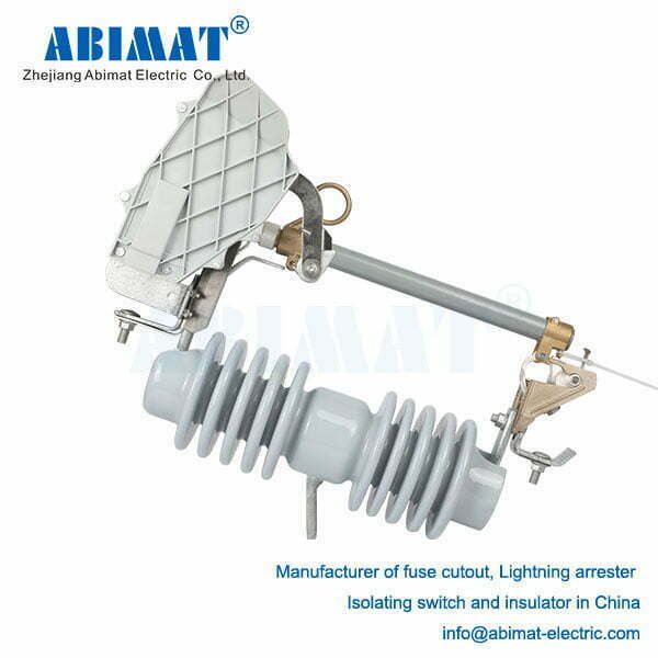
    Fuse cut-outs are the primary means of protecting against overcurrent in medium-voltage power distribution systems. They are typically used on transformers, feeders, and capacitor banks. Polymer-housed fuse cut-outs are now the most common; they have replaced porcelain ones due to their better performance and higher safety.

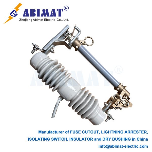
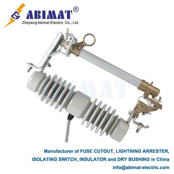
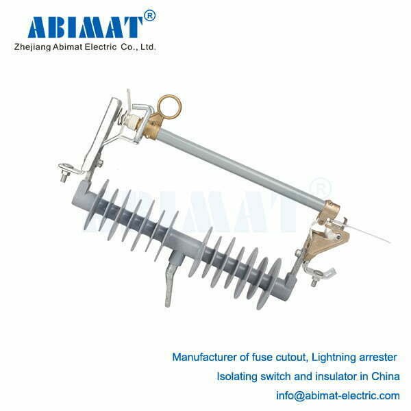
    A polymer fuse cut-out consists of several components. For example, there is the silicone rubber housing, which insulates, supports the device, and provides weather resistance. Then there is the pivoting fuse carrier, which holds the replaceable fuse link that limits current. There is also the base bracket, a hinged component that allows the carrier to drop down. Additionally, there are electrical contacts: upper and lower terminals for connecting to the circuit. The fuse link itself is critical—it responds to current and is set to operate at specific protection levels. When excessive current flows for an extended period, the fuse link melts, causing the carrier to pivot downward. This creates a visible gap and interrupts the circuit.

    Polymers offer numerous advantages. For one, they do not shatter—their structure remains intact without breaking into pieces or exploding when they fail. They also handle dirt and grime effectively. The silicone material, as you may know, is inherently water-repellent, preventing the formation of conductive films even in coastal or industrial areas. They are much lighter too—about 70% lighter than other types—making installation easier and reducing strain on the poles they are attached to. They can withstand impacts; a hard knock will not cause them to fall apart. They are also highly resistant to sunlight, enduring long exposure without significant damage such as tracking or erosion. Moreover, they require less maintenance: their self-cleaning surfaces mean dirt is less likely to cause problems.

    When selecting a polymer-housed fuse cut-out, several factors need consideration. The voltage rating is important—it should match the system’s operating voltage, such as 15.5kV or 27kV. Then there is the current rating, which refers to the continuous current it can handle, for example, 100A or 200A. Interrupting capacity is another key factor: it is the maximum fault current the device can interrupt, such as 12kA or 16kA. BIL (Basic Impulse Level) indicates the lightning voltage it can withstand—110kV or 150kV, for instance. Creepage distance, the leakage path, is set to handle dirt and grime in accordance with IEC 60815 standards. Mounting method also matters; they can be installed horizontally, vertically, or at an angle. Additionally, the fuse’s operating characteristic is relevant—it can be slow-acting (T-type) or fast-acting (K-type), depending on the application.

    These fuse cut-outs comply with major international standards. For example, they adhere to IEC 62271-111 and IEEE C37.41, which set guidelines for the design and testing of cut-outs. They also meet IEC 60282-1, which covers the performance of medium-voltage current-limiting fuses, and IEC 62217, the standard for testing polymeric housings.

    Rigorous testing ensures their reliability. Electrical testing includes checks with regular power frequencies and rapid electrical impulses. Mechanical testing evaluates the drop-out functionality and resistance to repeated loading. Environmental testing assesses performance under harsh conditions such as salt fog, ice accumulation, and prolonged sunlight exposure. Furthermore, fault interruption capability is verified to ensure they can stop faults when they occur.

    They have a wide range of important applications. They are used on overhead power lines operating at 4kV to 38kV, protect the primary side of transformers, function at feeder branching points, and safeguard capacitor banks.

    In summary, polymer-housed Abimat fuse cut-outs are crucial for protecting distribution networks. They can stop faults, indicate when they are isolated, and perform well in various environments. All of this, as you know, stems from the advanced silicone rubber used in their manufacture. These features make them safer and more reliable—traits of great importance. To obtain the best protection for the power grid, it is necessary to choose the right fuse cut-out. When making a selection, attention should be paid to its electrical parameters and the environmental conditions in which it will be used. Only in this way can its optimal performance be ensured.

    RW12-24F load break fuse cutout - ABIMAT ELECTRIC
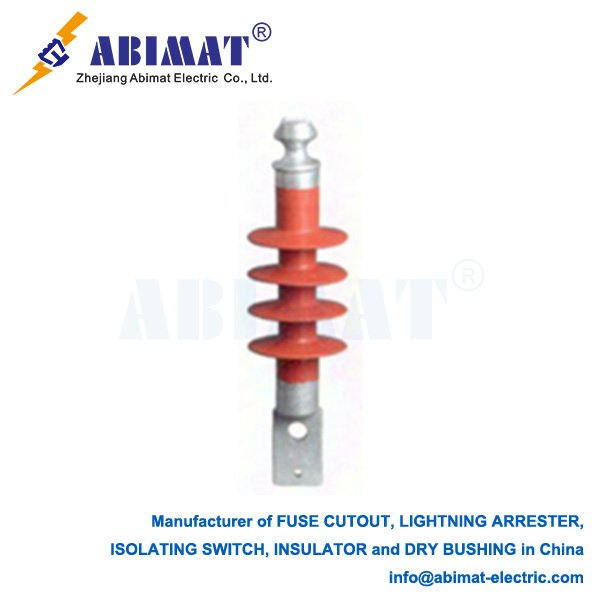
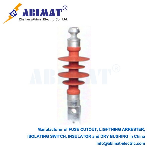
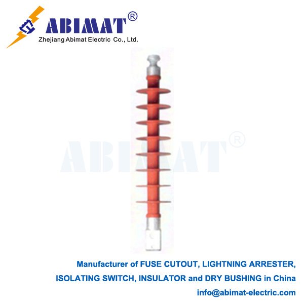
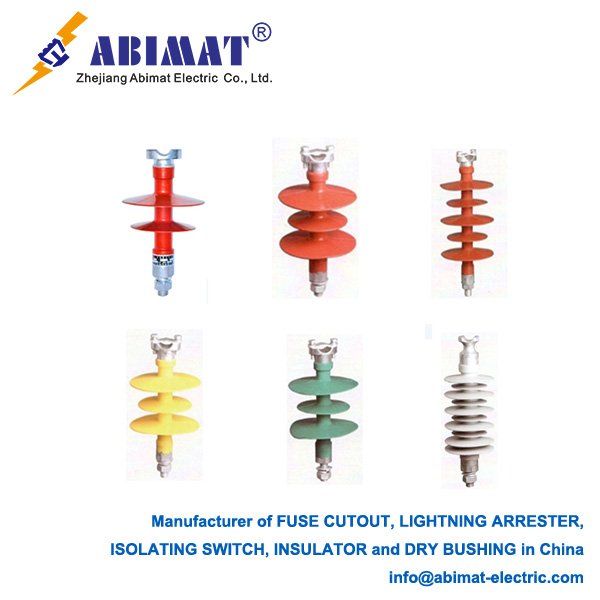
  • 33 kV Composite Pin Insulators: Technical Overview

    33 kV Composite Pin Insulators: Technical Overview

    33 kV Composite Pin Insulators: Technical Overview

    Design & Construction

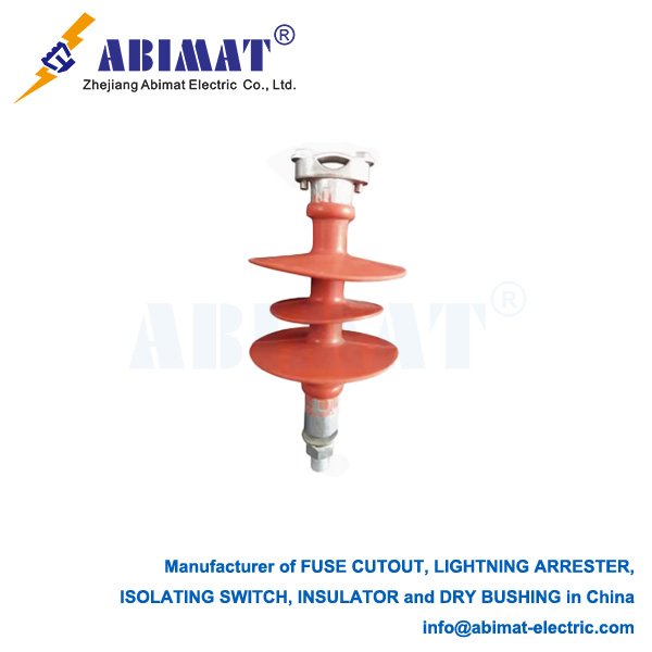
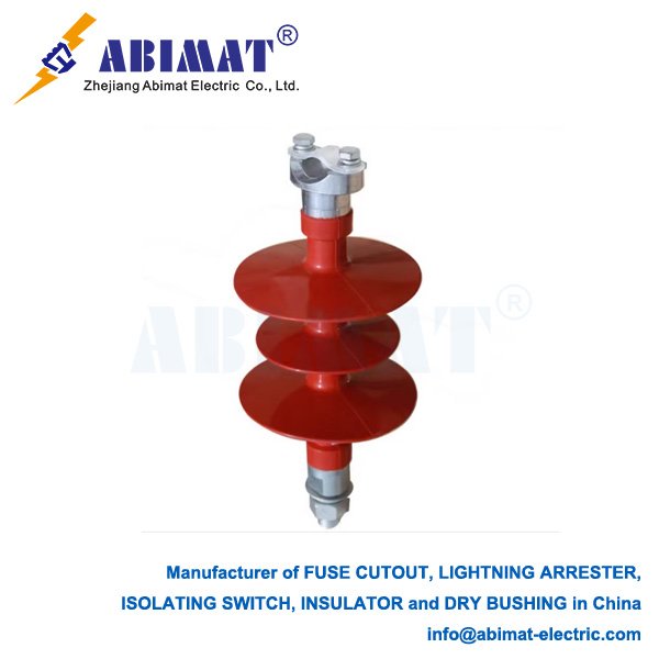
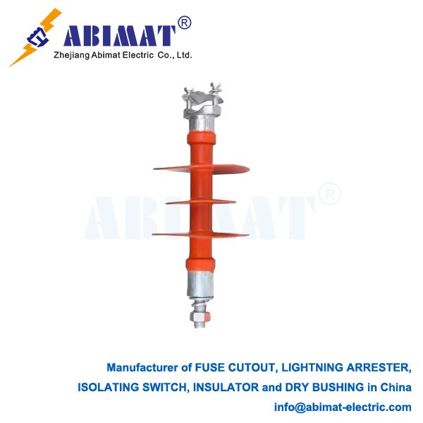
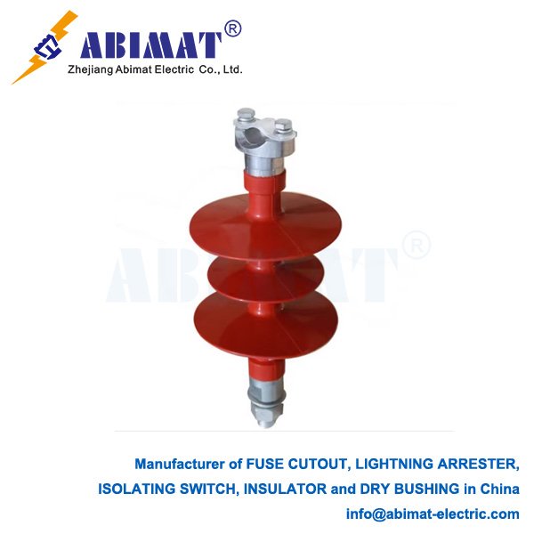
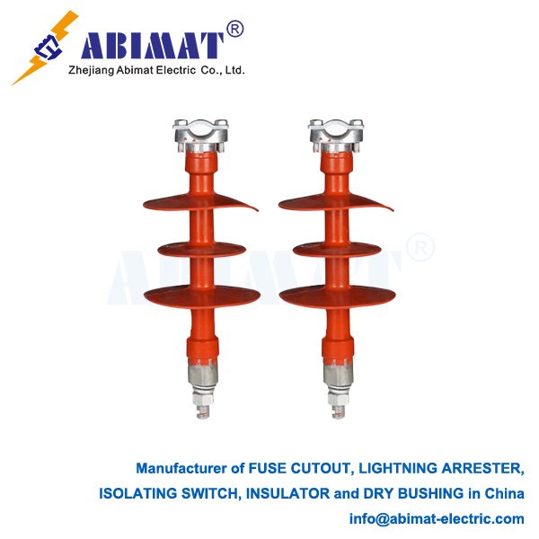
    33 kV composite pin insulators have three main parts. One part is the fiberglass-reinforced epoxy (FRP) core. It gives the insulator its mechanical strength. It can handle a minimum cantilever force of 12 kN, as set by IEC 61952. The core is a pultruded rod, with fibers running straight along its length—this helps it carry loads best.  

    Another part is the high-track silicone rubber housing. It is made of high-temperature vulcanized (HTV) silicone rubber. The sheds on it have a creepage distance of at least 31 mm per kV. This meets Class IV pollution standards from IEC 60815. It also has aluminum trihydrate (ATH) mixed in, which makes it better at resisting arcs.  

    The third part is the metal fittings. They are made of hot-dip galvanized steel or ductile iron. They are attached using compression crimping, which ensures they grip the core completely. The base has an M24 thread, following ANSI C29.9 standards.  

     Key Performance Advantages

    Composite insulators weigh 1.8–2.5 kg. Porcelain ones are heavier, 8–12 kg. This makes composite insulators 75% easier to install.  

    Composite insulators can handle a cantilever strength of at least 12 kN. Porcelain ones max out at 8 kN. So composite types are stronger mechanically.  

    When it comes to pollution, composite insulators meet Class IV standards. Porcelain ones only reach Class III. This means composite insulators work better in coastal areas.  

    Composite insulators don’t shatter when hit. Porcelain ones are brittle and break easily. This makes composite types better at standing up to vandalism.

    Silicone rubber, the material on composite insulators, has a useful trait. It can pass its water-repellent quality to dirt that builds up. Even in salty conditions, this keeps leakage current below 10 mA. This is checked in the IEC 60507 salt-fog test.  

    Composite insulators also handle earthquakes well. They have an elastic modulus of 40–50 GPa. This lets them take 0.5g seismic shaking without getting damaged.  

    They hold up well in sunlight too. The material used has no carbon black. After 5,000 hours of UV exposure—tested under ASTM G154—they still keep over 70% of their tensile strength.

    Electrical Performance

    Dry arcing distance is 330–380 mm.  

    They can withstand 70 kV for 1 minute at power frequency, as per IEC 60383.  

    They handle lightning impulses up to 170 kV BIL—this is tested with 10 positive and negative impulses.  

    Partial discharge is less than 5 pC at 1.2 times the rated voltage.  

    Manufacturing & Testing

    During production, the FRP rod first gets surface treatment—sandblasting and a primer. Then, HTV silicone is injection molded. Next, end fittings are attached with compression crimping. Finally, the δ-angle is checked to make sure it deviates by no more than 1°.  

    There are mandatory tests. For mechanical strength, they must handle 125% of the specified mechanical load for 1 minute. For the environment, they undergo 1,000 hours of salt mist and UV aging. For electrical performance, they pass a wet power frequency test at 50 kV. For the interface seal, they are immersed in water for 42 days, with weight gain kept below 0.05%.  

    Applications & Installation

    They meet IEC 61952, which covers insulators for overhead lines. They also fit IEC 62217, the standard for polymeric high-voltage insulators. They comply with ANSI C29.11/12 for composite distribution insulators and AS 3607, the Australian standard for composite insulators.  

    Failure Modes & Mitigation

    Core brittle fracture is prevented by ISO 9001-certified sealing processes. Shed erosion is limited to less than 2 mm deep after 1,000 kJ/kV energy stress. For vandalism, bird deterrents are used in areas with birds. For corrosion, coastal installations use zinc-thickened galvanizing (over 85 μm).  

    Standards Compliance

    They meet IEC 61952, which covers insulators for overhead lines. They also fit IEC 62217, the standard for polymeric high-voltage insulators. They comply with ANSI C29.11/12 for composite distribution insulators and AS 3607, the Australian standard for composite insulators.  

    Conclusion

    Abimat 33 kV composite pin insulators work better than traditional porcelain ones in terms of performance and weight. They don’t break easily, which makes the power grid more reliable. Their standardized designs work with systems worldwide. Choosing them according to IEC/ANSI standards and checking them yearly with infrared (looking for temperature differences over 8°C) helps them last over 30 years, even in tough environments.

  • Disconnect Switch Types: Essential Components for Power System Safety

    Disconnect Switch Types: Essential Components for Power System Safety

    Disconnect Switch Types: Essential Components for Power System Safety

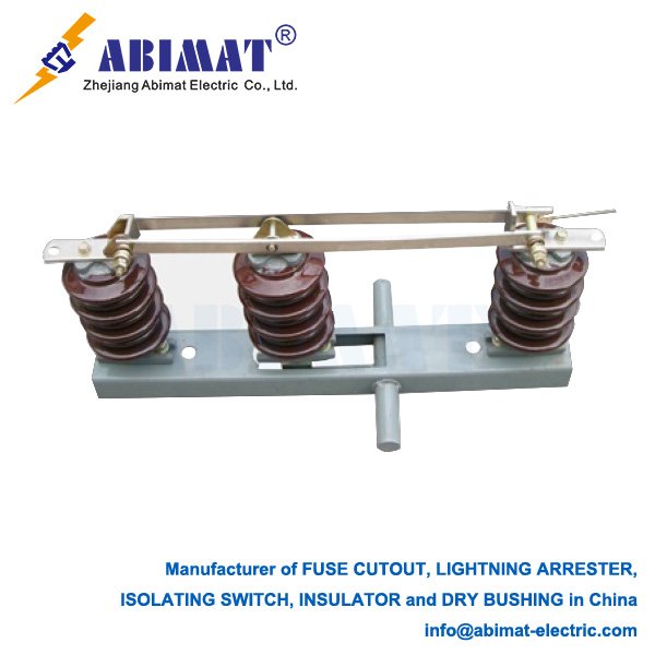
    Disconnect switches (disconnectors) provide critical visible isolation points in electrical power systems. They enable safe circuit de-energization for maintenance while enhancing operational safety. Unlike circuit breakers, disconnectors lack current-interrupting capability and operate only under no-load conditions or with minimal residual current. Various designs address specific voltage requirements, space constraints, and functional needs.

    Primary Types by Construction

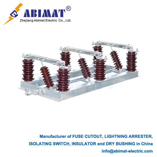
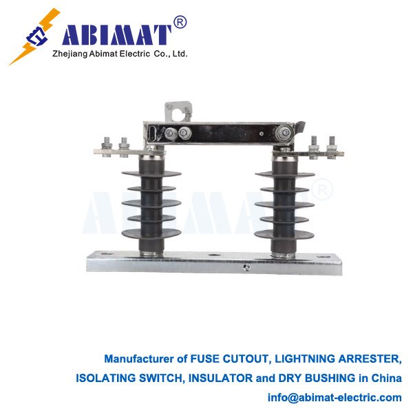
    The center-break type has a design where two insulator columns hold up a central arm that rotates and moves horizontally. It works well in outdoor substations, handling high voltage (HV) and extra high voltage (EHV) up to 800kV. It’s built strong, has a clear visible gap, and has a track record of working reliably, but it does need a lot of horizontal space, which is a downside. The double-break type has three insulator columns with a central rotating arm that creates two breaks at the same time. It’s used in HV and EHV setups where space is tight, can handle higher voltages for its height, and saves space, though its mechanism is more complex than single-break designs. The vertical-break (pantograph) type has a scissor-like mechanism that moves up and down from a lower stack of insulators. You’ll find it in HV and EHV substations where space is limited, needing very little horizontal space with an easy-to-see gap, but it does require a lot of vertical space to work, which is something to note. The horizontal swing type has a single insulator column with an arm that rotates horizontally on it. It’s used in medium voltage (MV) and HV outdoor setups, being mechanically simple and not needing too much space, but it can only handle lower voltage and current levels, which is a downside. The enclosed type has contacts inside insulated enclosures that can use air, SF₆, or vacuum, and often they can also break loads. They’re used in indoor or outdoor MV switchgear (up to 38kV) and ring main units (RMUs), being compact, able to stand up to weather, and letting you switch loads. But there’s no visible gap, and you need status indicators to know how they’re doing, which is a limitation.

    Functional Classification

    Non-load-breaking disconnectors only provide isolation when there’s no load. They have an important safety feature: a visible gap in the air. Load-breaking switches do more. They not only isolate circuits but can also stop load currents. They use methods to control arcs, like spring mechanisms or interruption with SF₆ or vacuum. They’re really important for switching transformers and capacitors in medium voltage systems. Fused disconnectors have current-limiting fuses built into their structure. This means they can both isolate circuits and protect against overcurrents, which is useful for transformers and capacitors. Grounding (or earthing) switches keep people safe by connecting isolated circuits to the ground. There are different kinds: standard ones, make-proof ones that can handle faults, and those built into main disconnectors. Busbar disconnectors are special designs. They connect equipment to busbars. Some have transfer switches, which let you move connections between live busbars.

    Selection Criteria  

    Several key factors affect how you choose a disconnector.

    System voltage is one. It sets the rules for insulation.

    Then there’s rated current. This covers how much current the disconnector can handle continuously and during short circuits.

    Space matters too. The amount of room you have is key for planning a substation’s layout well.

    What do you need the disconnector to do? Its job—like isolating circuits, breaking loads, grounding, or providing fused protection—matters a lot.

    Where will it go? Environmental conditions, such as how polluted the area is, the risk of earthquakes, and whether it’s for indoor or outdoor use, play a part.

    Safety can’t be ignored. You have to think about things like needing a visible gap between contacts and having proper grounding setups.

    And don’t forget standards. The disconnector must meet rules like IEC 62271-102 and IEEE C37.32.

    Conclusion

    Abimat disconnectors are essential for keeping power systems running safely. Picking the right kind—whether it’s a center-break, vertical-break, enclosed, or some special type—depends on the voltage class, what it needs to do, and the limits of where it will be installed. If you understand how each type works, you can use them correctly. This makes the system safer when doing maintenance and helps the whole network work more reliably.

  • Composite Post Insulators: Advanced Electrical Insulation Technology

    Composite Post Insulators: Advanced Electrical Insulation Technology

    Composite Post Insulators: Advanced Electrical Insulation Technology

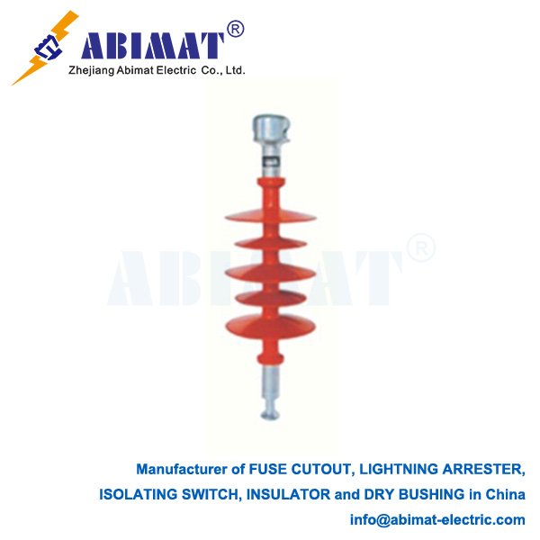
    Composite post insulators have changed high-voltage insulation for the better. They’ve taken the place of old porcelain and glass ones—in substations and power lines all over the world. These insulators do a key job: they keep live electrical parts separate from grounded structures. And they’re strong, too, giving great mechanical support.

    Design and Materials  

      I. FRP Core: A fiberglass-reinforced polymer rod delivering high mechanical strength in tension and compression without brittleness.
      II. Polymeric Housing: Silicone rubber or EPDM weathersheds protecting the core while providing necessary creepage distance.
      III. Metal End Fittings: Forged steel or aluminum alloy terminals crimped to the core for structural connections.

    Key Advantages  

    These insulators bring big perks for day-to-day use. They’re 80 to 90% lighter than porcelain ones. That makes them easier to install and eases the load on structures.  


    They handle dirt and grime really well. The silicone rubber they’re made of repels water. That stops conductive water films from forming—even in coastal areas, factories, or damp places.  


    They take a hit and keep going. The design doesn’t shatter. It can stand up to vandalism, earthquakes, and flying bits of debris.  


    They’re safer, too. Unlike brittle materials that can explode when they fail, these don’t do that.  


    And they need almost no upkeep. Even when they get dirty, their water-repelling property spreads out. That keeps them working like they should.

    Design Considerations  

    Picking the right one means checking a few things.  


    First, the mechanical load rating. That’s how strong it is against bending or squeezing—like 16kN or 32kN. You have to factor in safety, too.  


    Then there’s the creepage distance. That’s the length of the path where electricity might leak. It needs to match how dirty the site gets, following IEC 60815 rules.  


    The shed profile matters, too. The shape is designed to clean itself, and to stand up to dirt and ice.  


    Dry arcing distance is key. That’s the clear space between the end parts—needs to be enough to handle the electricity.  


    The core, made of FRP, has to hold up. It shouldn’t break easily or get damaged by acid.  


    For materials, silicone rubber is a good pick. It handles sunlight well and keeps repelling water over time.

    Applications  

    You’ll find them used in lots of places.  


    Substations, for one. They hold up things like disconnectors, circuit breakers, busbars, and surge arresters.  


    Transmission systems use them too. They support dead-end structures, jumper parts, and risers.  


    They work well in tough spots—coastal areas, industrial zones, places where earthquakes happen.

    Standards and Validation  

    Their performance gets checked through tests—following IEC 61952 for overhead lines and IEC 62231 for station posts.  


    They run mechanical tests. These check how they handle pulling, bending, and twisting.  


    Electrical tests are done too. They see how well the insulators stand up to regular power frequencies and sudden electrical jolts.  


    There are environmental tests. Think salt fog and temperature swings—they test how the insulators hold up.  


    And long-term aging tests. These put them under both electrical and mechanical stress, to see how they last over time.

    Conclusion

    Abimat composite post insulators are super reliable for today’s power networks. They’re light, tough against the environment, and don’t fail in a catastrophic way. That gives them an edge over older solutions, even over their whole lifespan. Pick the right one for the job, and it keeps the grid working its best—no matter the conditions.

  • 66kV Surge Arresters: Essential Protection for Medium-High Voltage Systems

    66kV Surge Arresters: Essential Protection for Medium-High Voltage Systems

    66kV Surge Arresters: Essential Protection for Medium-High Voltage Systems

    In 66kV power systems, keeping important gear safe is a must. Things like transformers, switchgear, and cables—they need protection from sudden voltage spikes.

    Surge arresters are the main line of defense here. The 66kV ones? They’re key for protecting medium-high voltage networks.

    Function and Operating Principle

    A 66kV surge arrester is a device that limits voltage. It gets installed between the phase and the ground, usually close to the equipment it’s protecting.  

    It works fast. When dangerous surge currents hit—from lightning or switching—this arrester sends them safely into the ground. That stops the voltage at equipment terminals from getting too high, keeping it at a safe level.  

    And here’s the key part: after doing its job, the arrester has to go back to a high-impedance state. That way, it can block the normal power frequency current from flowing through.

    Core Technology: Metal Oxide Varistors (MOVs)

    Modern 66kV arresters primarily use Zinc Oxide (ZnO) varistors. These sintered ceramic blocks exhibit highly nonlinear electrical behavior:

       At Normal Voltage: They act as insulators with minimal leakage current (typically microamperes).

       During Overvoltage: Their resistance drops dramatically within nanoseconds, conducting high surge currents (kA range) while clamping the voltage.

    Design Fundamentals

       Creepage Distance: Shed profiles are engineered to provide optimal creepage paths for specific pollution severity levels (per IEC 60815), often exceeding the protection offered by similarly rated porcelain units.

       Moisture Sealing: Precision sealing at the core/fitting/housing interfaces (using silicone gels/gaskets) is paramount to prevent moisture ingress and potential core brittle fracture (CBF).

       Core-End Fitting Interface: The mechanical connection between the fiberglass core and metal fitting is a critical engineered joint, designed for long-term integrity under constant mechanical load and environmental stress.

       Flame Retardancy: Quality composite insulators meet stringent self-extinguishing standards.

    Primary Applications

    A standard 66kV arrester with a polymer case has several parts.  


    First, the MOV stack. It’s made of zinc oxide discs connected in a line. These discs are rated to handle the system’s voltage and energy stress.  


    There’s a voltage grading system too. Inside, parts like grading rings make sure voltage spreads evenly across the MOV stack.  


    The polymer housing is important. It’s usually silicone rubber or something similar. It gives strength, resists dirt, repels water, and stops explosions—taking the place of old porcelain casings.  


    Hermetic seals are part of it. They keep moisture out, so the arrester works reliably for a long time.  


    And there’s mounting hardware. Brackets or flanges hold it securely when installed.

    Key Selection Parameters

    Choosing the correct 66kV arrester requires evaluating:

       System Voltage: Nominal voltage (66kV) and maximum continuous operating voltage (MCOV/Uc).

       Rated Voltage (Ur): Maximum temporary overvoltage (TOV) withstand capability for 10 seconds post-surge.

       Nominal Discharge Current (In): Peak 8/20 μs impulse current (e.g., 5kA, 10kA, 20kA) defining standard duty.

       Residual Voltage (Ures): Peak voltage during In discharge—the critical protective level. Lower Ures enhances protection but may increase cost/size.

       Energy Absorption: Maximum surge energy (kJ/kV of Ur) handled without failure.

       Pressure Relief (for porcelain): Safe gas venting capability during failure (less critical for polymer units).

    Importance and Compliance

    The right type of 66,000-volt surge arresters makes the power system much more dependable. They help keep important equipment safe. These arresters stop sudden high-voltage spikes from wrecking transformers and other devices. This protection cuts down on unexpected outages and repair time.


    These safety devices follow strict international rules. The main standard is called IEC 60099-4. This rulebook tells makers exactly how the arresters must work. It covers how well they perform their job. It explains how they are sorted into different types. It also lists all the tough tests they must pass before use.

    Conclusion

    Abimat 66kV surge arresters are key for protecting important power equipment. They use advanced zinc oxide varistor technology, all housed in strong polymer casings. These arresters act in an instant. They limit too-high voltages, keeping equipment safe at this voltage level. To get the best protection, you need to pick the right one. It depends on the system’s settings and the arrester’s ratings.

  • Fuse Cut-Outs: Essential Protection for 20kV Distribution Networks

    Fuse Cut-Outs: Essential Protection for 20kV Distribution Networks

    Fuse Cut-Outs: Essential Protection for 20kV Distribution Networks

    Fuse cut-outs provide critical overcurrent protection in 20kV overhead distribution systems. These field-proven devices combine fault interruption with visible isolation, safeguarding transformers, feeders, and cables against persistent overloads and short-circuit damage.  

    Operational Principle

    A standard cut-out features three integrated components:
      I. A polymer or porcelain insulator providing structural support and electrical isolation
      II. A pivoting fuse carrier housing the current-limiting fuse element
      III. A contact assembly with precision-engineered latch/release mechanics

    Fuse cut-outs are key safety tools on those big 20,000-volt power lines up in the air. They guard things like transformers and cables. They stop them from getting ruined when there’s a dangerous power surge or an electrical short. People trust these devices for a reason. They don’t just stop the problem—they also make it obvious when they’ve done their job.

    Technical Specs

    Voltage: Works with 20kV lines, up to 24kV at most.  

    Current it can handle nonstop: 100A, 200A, or 300A.  

    How much power it can shut off: At least 12.5kA (follows IEC 60282-1 rules).  

    Shock resistance: Can take 125kV jolts.  

    Fuse types: Fast-acting (K/T-type) or slower (S-type)—they respond to current over time differently.  

    Creepage: Needs to be 400mm or more for areas with medium pollution (check IEC 60815).  

    Main Jobs

    It clears problems downstream fast—within 0.5 to 5 cycles.  

    It keeps outages small, only hitting the part that’s affected.  

    You can see when it’s cut the power—there’s a physical sign.  

    It lets workers switch transformers by hand, using insulated sticks.  

    It limits how big a fault gets, thanks to the fuse acting quick.

    What Makes Them Better

    They clear transformer problems three times faster than reclosers.  

    They cost 40 to 60% less than circuit switchers—easy on the budget.  

    You can swap out the fuse links right in the field. Downtime? Less than five minutes.  

    Gravity helps them work, so they always disconnect safely if something goes wrong.  

    They fit right in with surge arresters and fault indicators—no extra hassle.  

    Where They Go to Work

    They protect transformers, the ones from 50kVA up to 2.5MVA, on the main side.  

    On radial circuits, you’ll find them every 3 to 5 poles, splitting the feeder into sections.  

    They stop capacitor banks from failing one after another when there’s a short circuit.  

    They’re good for critical spots: industrial power lines, mining setups, coastal networks.

    Selection and Maintenance

    – Fuse rating must withstand transformer inrush (12× nominal for 0.1s)  

    – Interrupting capacity exceeding available fault current  

    – UV-stabilized EPDM seals for polymer housings  

    – IEC 61936-compliant creepage for polluted environments  

    Maintenance Protocol:

      I. Annual infrared scanning of contact points
      II. Verification of carrier drop angle (≥90° from horizontal)
      III. Dry-period insulator cleaning
      IV. Fuse replacement after two operations
      V. Operational testing with load-break tools

    Standards Conformance

     – IEC 60282-1 (High-voltage fuses)  

    – ANSI C37.41 (Distribution cutouts)  

    – IEEE 1410 (Expulsion fuse guidance)  

    Operational Significance

    The Abimat  20kV fuse cut-out remains indispensable in modern distribution systems. Its integrated fault interruption, positive disconnection visibility, and manual switching capabilities deliver unparalleled cost-to-reliability ratios. Proper fuse coordination—considering available fault currents and equipment withstand characteristics—prevents unnecessary upstream outages. When maintained per manufacturer guidelines and installed with appropriate animal guards and surge protection, these devices provide decades of service across utility, industrial, and renewable energy applications, forming the first line of defense against electrical faults in overhead networks.