Author: Zhou

  • 11 kV Disconnecting Switch: Critical Safety Component in Medium-Voltage Systems

    11 kV Disconnecting Switch: Critical Safety Component in Medium-Voltage Systems

    11 kV Disconnecting Switch: Critical Safety Component in Medium-Voltage Systems

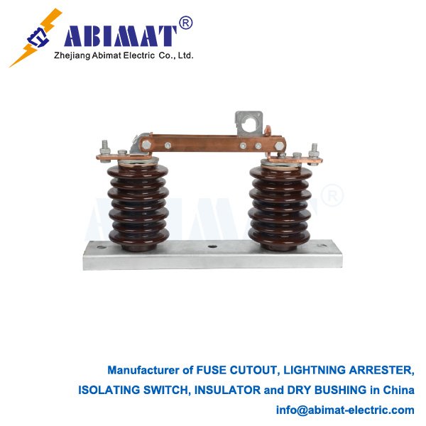
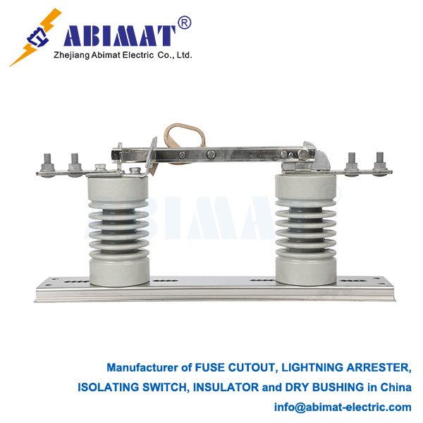
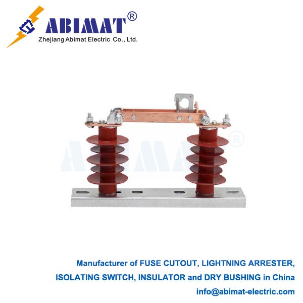
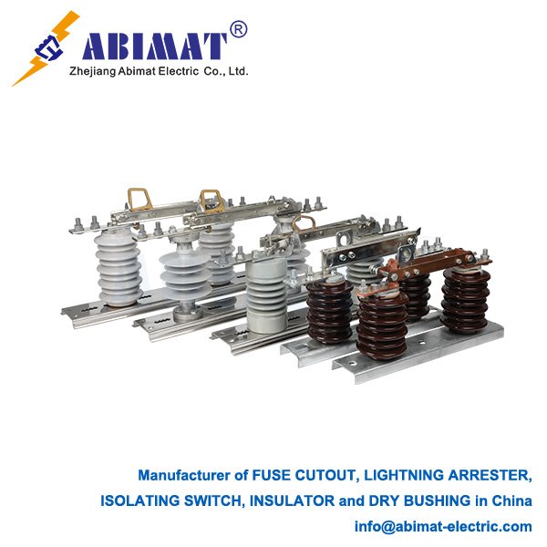
    The abimat 11 kV disconnecting switch (disconnector) provides fundamental safety isolation in medium-voltage distribution networks. Functionally distinct from circuit breakers, it establishes a visible isolation gap compliant with IEC 62271-102 to enable safe equipment maintenance, system reconfiguration, and personnel protection.  
    Functional Requirements & Design Standards

    Core Functions:  

    – Establish visible air gap isolation (minimum 150 mm phase clearance)  

    – Facilitate safe isolation of transformers, cables, and switchgear  

    – Enable feeder sectionalizing without network de-energization  

    – Provide integrated earthing interface per IEC 61936-1  


    Technical Parameters:  

    – Rated Voltage: 12 kV (IEC) / 15 kV (ANSI)  

    – Continuous Current: 630A to 1250A  

    – Short-time Withstand: 20 kA rms for 3 seconds  

    – Impulse Withstand: 95 kV BIL (Basic Impulse Level)  

    – Operating Duty: Manual rotary mechanism or motorized actuator  

    Critical Design Elements

    Contact Configuration:  

    – Single-break type: Horizontal rotary blade (compact AIS applications)  

    – Double-break type: Vertical-break assembly (enhanced dielectric performance)  

    – Self-aligning contacts: Copper-tungsten arcing tips maintaining contact resistance ≤50μΩ  


    Insulation Coordination:  

    – Phase-to-phase clearance: ≥150 mm  

    – Composite insulators: Silicone rubber housing (Pollution Degree IV per IEC 60815)  

    – Minimum creepage distance: 31 mm/kV  


    Safety Integration:  

    – Mechanical interlocks preventing load-break operation  

    – Dual-padlocking provisions (ISO 14119 compliant)  

    – Mechanically coupled position indicators  

    Mandatory Operational Protocols

    Prohibited load interruption: Limited switching capability to:  

       – Transformer magnetizing currents ≤5A  

       – Capacitive charging currents ≤3A (IEC 62271-102 Annex C)  

    Sequential isolation procedure:  

       – De-energize circuit via upstream protective device  

       – Verify de-energization  

       – Operate disconnector  

       – Engage earthing blades  

    Application Profiles

    Distribution Networks:  

    – Transformer primary/secondary isolation  

    – Ring Main Unit feeder selection  

    – Shunt capacitor bank disconnection  


    Industrial Power Systems:  

    – 11 kV motor feeder isolation  

    – Generator circuit isolation  

    – Bus section segregation  


    Overhead Line Applications:  

    – Pole-mounted disconnectors (IP55 environmental rating)  

    – Air-Insulated Switchgear disconnection points  

    Maintenance & Verification

    Performance Validation:  

    – Contact erosion inspection (max. 20% material loss)  

    – Operating torque measurement (≤150 Nm)  

    – Insulation resistance testing (≥100 MΩ at 5 kV DC)  

    – Blade alignment verification (±1.5° tolerance)  


    Type Test Requirements (IEC 62271-1):  

    – Power frequency withstand: 28 kV RMS for 1 minute  

    – Lightning impulse withstand: 95 kV peak  

    – Mechanical endurance: 1,000 operating cycles  

    – Temperature rise test: 65°C max. at rated current  

    Technology Evolution

    – Motorized operation: SCADA-integrated actuators  

    – Condition monitoring: Embedded temperature/position sensors  

    – Hybrid switchgear: Vacuum interrupter integration for load-break capability  

    – GIS variants: SF₆-insulated compact designs  
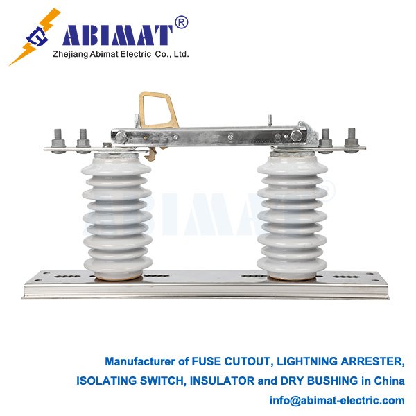
  • 115 kV Disconnect Switch: Essential Component for Transmission System Safety & Maintenance

    115 kV Disconnect Switch: Essential Component for Transmission System Safety & Maintenance

    115 kV Disconnect Switch: Essential Component for Transmission System Safety & Maintenance

    Operational Principle & Functional Design

    In 115 kV high-voltage transmission systems, the disconnect switch (disconnector) fulfills a critical safety function distinct from circuit breakers. Although incapable of interrupting load or fault currents, its core purpose is establishing a visible air gap to safely isolate circuits, equipment, and bus sections during maintenance, commissioning, or system reconfiguration – ensuring personnel safety and operational flexibility.  

    Core Functions & Operational Significance

    I.Visible Air Gap Isolation:  

        Provides physical circuit separation verifiable at ground level. This unambiguous break is the primary safety assurance for personnel working on de-energized equipment (lines, transformers, breakers).  

    II.Selective Circuit Segregation:  

        Enables isolation of individual feeders, transformers, or bus sections without de-energizing entire substations. Critical for:  

        – Equipment maintenance/repair  

        – Power flow rerouting (contingency management)  

        – Pre-energization testing of new assets  

    III.Integrated Grounding Interface:  

        Often incorporates grounding blades. After main blade opening, grounding blades earth the isolated section, providing a complementary critical safety layer against accidental re-energization or induced voltages.  

    Design & Technical Specifications

       Voltage Rating: Certified for 115 kV nominal voltage with defined dielectric withstand (BIL) and clearance margins.  

       Continuous Current Rating: Typically 1200A to 3000A+ at 115 kV.  

       Operating Mechanism:  

        – Gang-operated (standard): Motorized/manual ground-level drive with insulating linkages for simultaneous pole operation.  

        – Independent Pole Operation (IPO): Used where phase-segregated operation is justified.  

       Blade Architectures:  

        – Center-Break: Rotating blades pivot from central hinge.  

        – Double-Break: Horizontal/vertical motion creates two series breaks per phase.  

        – Vertical-Break: Gravity-assisted opening; preferred for compact substation layouts.  

       Auxiliary Arcing Contacts: Interrupt magnetizing/capacitive currents (e.g., transformer no-load current) without damaging main contacts.  

       Corona Suppression: Contoured contacts/hardware minimize RF noise and ionization at operating voltage.  

       Ice-Rated Operation: Meets IEC 62271-307 ice-breaking capacity requirements.  

    Critical Safety Protocols

       Load Break Prohibition:  

        115 kV disconnect switches MUST NOT interrupt load current. Operation under load causes sustained arcs resulting in catastrophic equipment failure and personnel hazard. Operation permitted ONLY when:  

        – Upstream breaker has de-energized the circuit, OR  

        – Current is below arcing contact rating (verified by calculation/procedure).  

       Mandatory Interlocking:  

        Prevents:  

        – Operation with closed circuit breaker (load condition)  

        – Closing onto energized faulted circuits  

        – Grounding blade engagement with closed main blades  

       Dielectric Clearances:  

        Phase-to-phase/phase-to-ground clearances and insulator creepage distances comply with IEC 61936 for polluted environments.  

    Typical 115 kV Applications

       Transformer primary/secondary isolation  

       Transmission line feeder isolation  

       Bus sectionalization (fault containment)  

       Circuit breaker bypass configurations  

       Shunt reactor/capacitor bank connections

    Conclusion

    The ABIMAT 115 kV disconnect switch is an indispensable asset in transmission infrastructure. Its value resides in establishing verifiable physical isolation – the foundational safety prerequisite for high-voltage work. By enabling selective de-energization and system reconfiguration, it ensures grid reliability while protecting personnel. Strict adherence to operational constraints (notably load-break prohibition) and robust interlocking are non-negotiable for safe deployment. Design evolution prioritizes enhanced environmental resilience, reduced maintenance, and integrated condition monitoring.  

  • Distribution Fuse Cutouts: Critical Protection in Overhead Networks

    Distribution Fuse Cutouts: Critical Protection in Overhead Networks

    Distribution Fuse Cutouts: Critical Protection in Overhead Networks

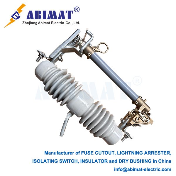
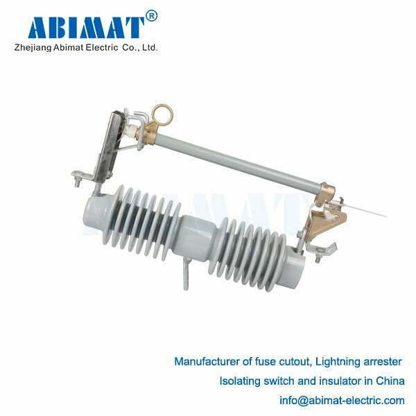
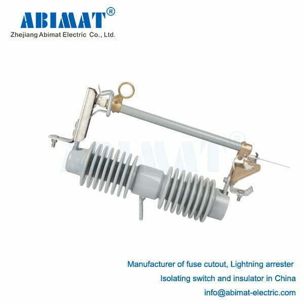
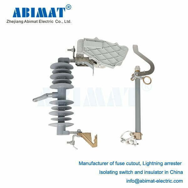
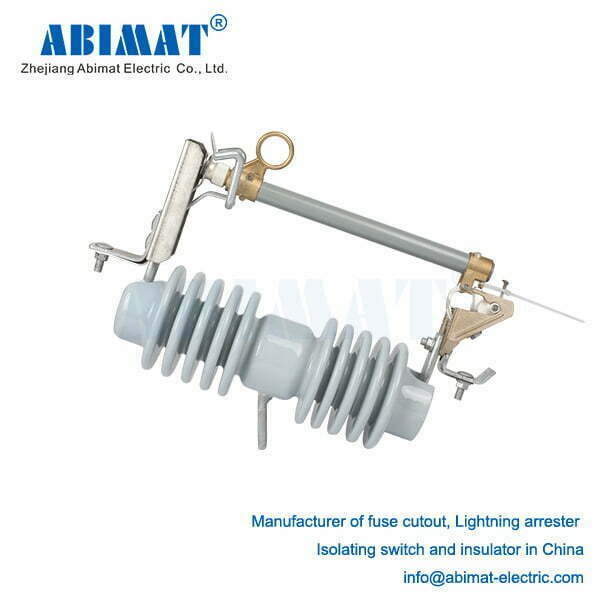
    The distribution fuse cutout serves as a primary protective device in overhead electrical distribution systems. It functions as a fused disconnecting switch, delivering essential overcurrent protection, fault isolation, and visible circuit breaking for maintenance operations. This safeguards transformers, feeders, and downstream equipment.

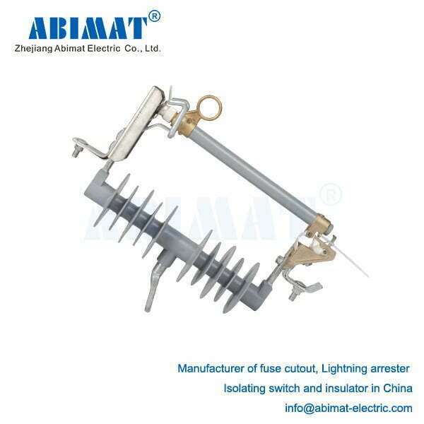
    HRW12 - 24kV polymer fuse cutout ABFCO121 series - ABIMAT ELECTRIC

    Core Components & Operation

    I. Insulator: Provides electrical isolation between live components and the grounded support structure (pole/crossarm), manufactured from porcelain or polymer.

    II. Fuse Holder (Tube): A hinged assembly housing the fuse link, designed to drop open visibly (“cut out”) upon fuse operation.

    III. Fuse Link: The calibrated sacrificial element melting under defined overcurrent conditions. Principal types:

           Expulsion Links: Generate de-ionizing gas via a fiberglass liner to extinguish the arc post-melting.

           Current-Limiting Links: Utilize sand filler for rapid arc quenching, minimizing let-through fault energy.

    IV. Contacts: Maintain electrical connection between the incoming line conductor and outgoing load conductor (e.g., transformer primary).

    V. Mounting Bracket: Secures the cutout assembly to pole hardware.

    Primary Protective Functions

    I. Overcurrent & Fault Interruption: The paramount role. Downstream faults (short circuits, severe overloads from lightning, equipment failure, or contact) induce excessive current flow. The precisely sized fuse link melts, creating an open circuit. This isolates the faulted section upstream of the cutout, preventing destructive fault currents from propagating toward substations and damaging upstream assets like transformers and main feeders.

    II. Targeted Sectionalizing: Cutouts strategically segment distribution networks. A blown fuse physically and visibly isolates the specific faulted downstream section (e.g., lateral feeder, transformer tap). This enables utilities to:

           Locate the fault area rapidly (identified by the open cutout).

           Restore power swiftly to unaffected upstream customers.

           Isolate the faulted zone safely for repair crews.

    III. Transformer Protection: Standard installation on distribution transformer primaries protects against:

           Destructive internal transformer faults.

           Severe secondary-side faults or overloads reflected to the primary.

    Operational Characteristics

       Fusing Action: Passive, automatic operation based strictly on overcurrent magnitude and duration (per the link’s time-current characteristic curve).

       Drop Open Design: The mechanical drop-open of the fuse holder provides unambiguous ground-level indication of fuse operation and circuit status, critical for safety and fault location.

       Manual Switching: Line crews use insulated hot sticks to manually open the holder (de-energizing downstream equipment for maintenance, providing visible air gap) or close it (re-energizing after repairs/replacement).

       Coordination: Fuse links are meticulously sized and typed to coordinate with upstream devices (reclosers, breakers) and downstream fuses, ensuring the closest device to the fault operates first to minimize outage scope.

    Evolution & Specialized Types

      Solid Material Links: Modern alloys enhance durability and performance consistency versus older tin/lead links, reducing nuisance operations.

       Electronic Fuse Cutouts (EFCs): Integrate sensors, controls, and communication. EFCs deliver:

           Remote fault indication/location;

           Precise fault current recording;

           Programmable protection curves;

           Potential for automated sectionalizing/reclosing coordination.

       Bay-O-Net® Links: Utilize dual series fuse elements within the tube, optimizing transformer protection. A lower-melting-point “protector” link responds to internal faults, while the main “fuse” link handles external faults.

    Critical Importance

    The distribution fuse cutout remains indispensable for safe, reliable, and manageable overhead distribution. Its fundamental strengths are:


       Automatic Fault Isolation: Rapid damage containment.

       Visual Fault Indication: Expedited crew response.

       Safe Isolation Point: Facilitated maintenance.

       Selective Coordination: Minimized outage impact.

    Conclusion

    By preventing fault propagation, enabling targeted restoration, and protecting critical assets, ABIMAT fuse cutouts are vital to distribution system resilience. Ongoing advancements in fuse link technology and electronic integration ensure their continued effectiveness within modern power grids.

  • The Distribution Cutout: A Critical Guardian of Power System Integrity

    The Distribution Cutout: A Critical Guardian of Power System Integrity

    The Distribution Cutout: A Critical Guardian of Power System Integrity

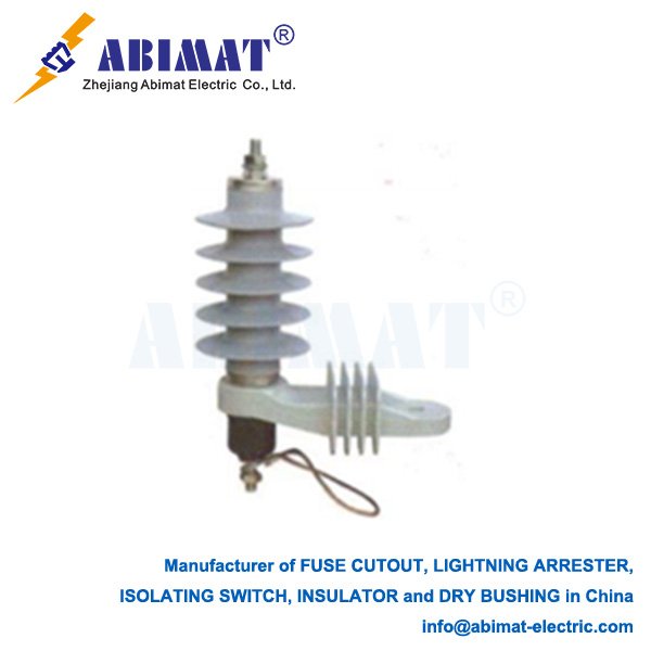
    Within overhead electrical distribution networks, the distribution cutout serves as a fundamental and indispensable protective device. Often appearing as a simple component mounted on utility poles, its role in safeguarding infrastructure, ensuring reliability, and enabling safe operations is paramount. This fused switch acts as the frontline defense against damaging overcurrents, primarily caused by faults.

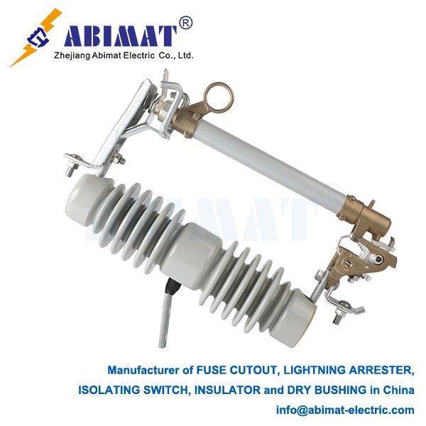
    RW12 - 33kV fuse cutout ABFCO122 series detail 1 - ABIMAT ELECTRIC

    Anatomy and Function

    A standard distribution cutout comprises several key elements:

    I.Mounting Bracket: Secures the assembly to the pole or crossarm.

    II.Insulator: Provides electrical isolation between live components and the grounded support structure, typically made of polymer or porcelain.

    III.Fuse Holder (Fuse Tube): The hinged component housing the replaceable fuse link. Its design often causes it to drop open visibly upon fuse operation.

    IV.Fuse Link: The sacrificial element calibrated to melt (“blow”) under specific overcurrent conditions, interrupting the circuit.

    V.Contacts: Provide electrical connection points for the incoming line conductor and the outgoing conductor feeding downstream sections or transformers.

    Core Protective Functions

    I.Overcurrent and Fault Interruption: This is the primary function. Downstream faults—caused by lightning, equipment failure, animal contact, or falling branches—result in excessive current. The precisely sized fuse link melts under this abnormal current, creating an open circuit. This isolates the faulted section upstream of the cutout, preventing damage propagation towards the substation and protecting upstream equipment like transformers and lines.

    II.Isolation/Sectionalizing: Cutouts act as strategic sectionalizing points. A blown fuse physically and visibly isolates the faulted downstream section (e.g., a lateral feeder or customer tap). This enables utilities to quickly locate the fault (based on the open cutout) and restore power to unaffected upstream areas while downstream repairs proceed. The visibly open fuse holder provides a clear indicator for line crews.

    III.Transformer Protection: Cutouts are almost universally installed on the primary side of distribution transformers. They protect the transformer from damaging internal faults and severe secondary-side overloads.

    Operation and Key Features

       Fusing: Cutouts use expulsion-type fuse links. When the link melts, an arc forms within the fuse tube. The tube liner (often fiberglass) generates de-ionizing gases under the arc’s heat, rapidly extinguishing it and safely clearing the fault.

       Visible Open Indication: Most cutout designs cause the fuse holder to drop open or swing down by gravity after fuse melting and interruption complete. This provides a highly visible, unambiguous ground-level indication of operation and an open circuit.

       Manual Switching: Cutouts also serve as manual disconnect switches. Line crews can safely open the fuse holder using an insulated “hot stick” to de-energize a downstream section for maintenance, providing visible air gap isolation.

    Evolution and Variations

    While traditional fused cutouts dominate, variations exist:

       Solid Material Fuse Links: Offer improved durability and environmental resistance over older tin or lead alloy links.

       Electronic Cutouts (EFC – Electronic Fused Cutout): Integrate sensors and communication modules. They provide remote fault indication, precise fault current measurements, and potentially automated reclosing, enhancing grid intelligence and restoration speed.

       Recloser-Cutout Combinations: Used where more sophisticated protection coordination is needed on lateral taps.

    Conclusion

    The ABIMAT distribution cutout, though mechanically straightforward, is a cornerstone of safe, reliable, and manageable overhead power distribution. Its ability to automatically detect and isolate faults, provide vital visual indication, and serve as a manual isolation point makes it an essential component. By preventing fault currents from causing widespread damage and enabling rapid sectionalizing, these devices minimize outage duration and extent, underpinning the resilience of the electrical grid. Continuous refinement in fuse technology and electronic integration ensures this critical device remains effective in modern power systems.

    RW12- 33kV fuse cutout ABFCO122 series - ABIMAT ELECTRIC
  • Cut-Out Fuse Links: Essential Protection in Electrical Distribution

    Cut-Out Fuse Links: Essential Protection in Electrical Distribution

    220kV Lightning Arresters: Guardians of High-Voltage Transmission Systems

    Introduction

    Fuse cutout links, commonly known as “distribution cutouts” or “fuse cutouts,” are fundamental protective devices found throughout overhead electrical distribution networks, typically handling voltages up to 38 kV. They serve two critical purposes: providing reliable overcurrent protection for transformers, feeders, and laterals, and acting as a clear, manual disconnecting point for circuit isolation and maintenance. Their robust design and operational simplicity make them indispensable components of utility infrastructure.

    Core Function and Operating Principle

    The primary role of a cut-out fuse link is straightforward: to safely interrupt excessive current caused by faults (such as short circuits or sustained overloads) within the protected circuit segment. This action protects downstream equipment like transformers from severe damage and prevents fault currents from spreading, enhancing overall system reliability.


    Operation relies on a precisely calibrated fusible element housed within the removable fuse link assembly:

    I.Normal Operation: Under normal load current within its rated capacity, the fusible element remains intact, allowing uninterrupted power flow through the fuse holder (fuse tube).

    II.Fault Condition: When current exceeds the fuse link’s rating for a predetermined duration, the fusible element rapidly melts (“blows”) due to Joule heating.

    III.Arc Initiation & Extinction: Melting the element initiates an electric arc inside the fuse tube. The tube, often lined with a deionizing material such as fiberglass or boric acid, generates gases under the intense heat of the arc. This gas generation creates high internal pressure.

    IV.Expulsion Effect: The pressurized gases are expelled forcefully through vents at the bottom or ends of the tube. This controlled expulsion elongates, cools, and deionizes the arc plasma, effectively quenching it and interrupting the fault current. The gas expulsion often produces a noticeable audible report (a “bang”).

    V.Visible Indication & Isolation: After operation, the fuse link assembly visibly drops open (in “drop-out” style cutouts) or shows other clear external signs (like a melted indicator). This provides immediate visual confirmation of operation and creates a safe, visible air gap isolating the downstream circuit.

    Key Construction Components

    I.Fuse Holder (Tube): The insulating housing (typically made of porcelain or polymer) contains the fusible element and arc-quenching medium. It’s designed to withstand arc energy and channel the expulsion gases.

    II.Removable Fuse Link: This core component includes:

           Fusible Element: A precisely engineered wire or strip (e.g., silver, tin, copper) with a specific time-current characteristic (TCC).

           Arc-Quenching Medium: Lining material surrounding the element that generates arc-extinguishing gases.

           Strain Wire/Assembly: Provides mechanical tension to ensure proper operation and drop-out.

           Terminations: Electrical contacts for connection within the cutout body.

    III.Cutout Body (Mounted Assembly): The base assembly mounted on the pole or crossarm, typically consisting of:

           Insulating Bracket/Housing: Supports the fuse holder and provides electrical insulation.

           Upper & Lower Contacts: Clamp onto the fuse holder terminals to connect it in series with the circuit.

           Hinge & Latch Mechanism: Allows the fuse holder to pivot open after operation and facilitates easy insertion and removal.

    IV.Mounting Insulator: Provides structural support and electrical isolation from the pole or structure.

    Primary Applications

    Cut-out fuse links are primarily used for:

       Transformer Protection: Protecting pole-mounted and pad-mounted distribution transformers.

       Feeder/Lateral Protection: Safeguarding main distribution feeders or branch laterals from faults.

       Sectionalizing: Dividing circuits into protected zones to minimize outage impact and aid fault location.

       Capacitor Bank Protection: Protecting switched capacitor banks on distribution circuits.

       Tap Protection: Protecting circuits tapped off a main feeder.

    Transmission-Specific Design Features

    – Grading Rings: Control electric field distribution across multi-unit columns.  

    – Sealed Housing: Nitrogen/SF₆-filled porcelain or silicone rubber composite prevents moisture ingress.  

    – Explosion Containment: Porcelain housings include frangible caps; polymer uses fiber-reinforced burst membranes.  

    – Seismic Rating: Certified for ≥ 0.5g horizontal acceleration (IEEE 693).

    Advantages

     High Interrupting Capacity: Capable of safely interrupting very high fault currents common on distribution systems.

       Reliable & Proven: Simple, robust, and time-tested technology.

       Clear Visual Indication: Provides unambiguous confirmation of operation and fault location.

       Effective Isolation: Creates a visible, safe air gap essential for maintenance safety.

       Cost-Effective: Relatively inexpensive compared to alternatives like reclosers for their core applications.

       Easy Replacement: Line crews can quickly replace fuse links to restore service.

    Considerations

     Single-Shot Device: Requires manual replacement after operation.

       Coordination: Careful selection of fuse link ratings and TCCs is essential for proper coordination with upstream/downstream protection devices (reclosers, other fuses).

       Environmental Factors: Performance can be influenced by ambient temperature, wind, and insulator pollution.

       Expulsion Effects: Requires adequate clearance for safe gas expulsion; unsuitable for confined indoor spaces.

    Conclusion

    ABIMAT Fuse cutout links remain a cornerstone technology in overhead electrical distribution. Their ability to reliably interrupt fault currents, provide clear visual indication and safe isolation, and protect critical assets like transformers ensures their continued importance. A solid understanding of their operating principle, construction, and application is fundamental for engineers and technicians involved in designing, operating, and maintaining safe and reliable power distribution networks. They represent a practical and effective solution for managing electrical faults.

  • 220kV Lightning Arresters: Guardians of High-Voltage Transmission Systems

    220kV Lightning Arresters: Guardians of High-Voltage Transmission Systems

    220kV Lightning Arresters: Guardians of High-Voltage Transmission Systems

    Introduction

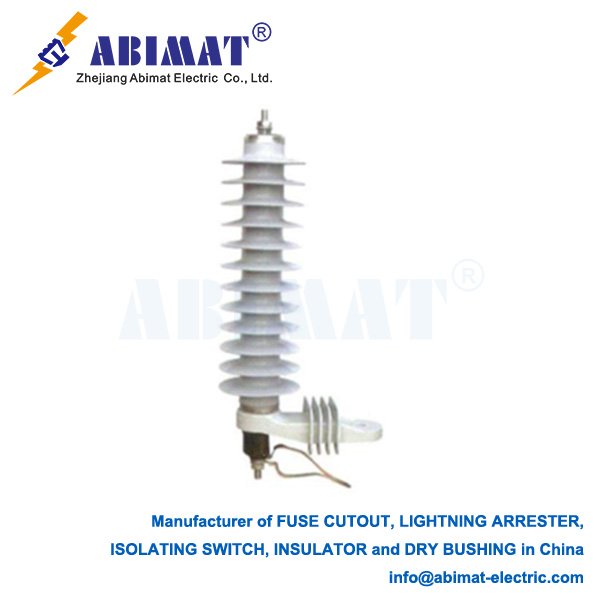
    220kV lightning arresters (surge arresters) serve as critical protective components in extra-high-voltage (EHV) transmission networks. Operating at the backbone of national power grids, they defend multi-million-dollar equipment against transient overvoltages from lightning strikes, switching operations, and system faults. Their failure can cascade into widespread blackouts, making precise engineering and selection paramount for grid resilience.

    Core Operational Principle

    These arresters function as voltage-controlled switches between phase conductors and ground:  

    – High-Impedance State: At normal operating voltage (< threshold), they act as open circuits (leakage current < 1 mA).  

    – Low-Impedance State: During transient overvoltages, they switch to low resistance within < 100 nanoseconds, creating a low-impedance path to ground. Crucially, they clamp the residual voltage (Up) across protected equipment to a safe value below its Basic Lightning Impulse Level (BIL). Post-event, they autonomously reset.  

    Technology: Advanced ZnO Varistor Columns

    Modern 220kV arresters utilize stacked Zinc Oxide (ZnO) varistor columns housed in porcelain or composite polymer housings. Each varistor disc contains ZnO grains doped with Bi₂O₃, Sb₂O₃, CoO, and MnO₂, forming billions of grain-boundary p-n junctions:  

    – Normal Voltage: Junctions act as barriers (high resistance).  

    – Surge Voltage: Electric field-induced quantum tunneling collapses junction resistance.  

    – Self-Restoration: Junctions reform post-surge

    Key Advantages for EHV Applications:

    – Ultra-nonlinear V-I characteristics  

    – Energy absorption capacity > 10 kJ/kV of Ur  

    – Response time ≤ 25 ns  

    – Zero power-frequency follow current  

    – Voltage grading rings optimize electric field distribution  


    Critical Performance Parameters & Selection  

    (Per IEC 60099-4 / IEEE C62.11)

    ParameterTechnical Significance220kV System Values
    Rated Voltage (Ur)Max temporary power-frequency overvoltage (10s withstand). Must exceed maximum Temporary Overvoltage (TOV).180kV–216kV (Ur ≥ 1.25 × nominal phase-ground voltage for effectively grounded systems)
    MCOVMax continuous RMS phase-ground voltage. Critical for thermal stability.146kV–160kV (For 220kV systems: Vₗ₋₉ = 127kV)
    Nominal Discharge Current (In)Standard 8/20 µs lightning current rating.10kA (Standard)
    20kA (High lightning density)
    Line Discharge ClassEnergy handling from line switching surges (IEC).Class 4-5 (≥ 20kJ/kV of Ur)
    Lightning Impulse Protective Level (Up)Max residual voltage at 8/20 µs current. Must be ≥25% below equipment BIL.≤ 550kV (For 1050kV BIL transformers)
    Switching Impulse Protective Level (SPL)Residual voltage at 30/60 µs or 100/1000 µs wave.≤ 450kV (Critical for breaker TRV coordination)
    Steep Front Protective LevelResidual voltage at 1.2/50 µs wave (GIS close-in strikes).≤ 650kV
    Pressure Relief RatingMax short-circuit current withstand upon failure. Mandatory for safety.40kA–63kA (Matches substation fault level)
    Creepage DistancePollution performance (IEC 60815).≥ 6,300mm (Very Heavy Pollution)


    Transmission-Specific Design Features

    – Grading Rings: Control electric field distribution across multi-unit columns.  

    – Sealed Housing: Nitrogen/SF₆-filled porcelain or silicone rubber composite prevents moisture ingress.  

    – Explosion Containment: Porcelain housings include frangible caps; polymer uses fiber-reinforced burst membranes.  

    – Seismic Rating: Certified for ≥ 0.5g horizontal acceleration (IEEE 693).

    Strategic Applications in 220kV Networks

    I.Transformer Protection: Directly connected to 220kV bushings (BIL coordination essential).  

    II.Substation Entrances: First protection point for incoming transmission lines.

    III.Shunt Reactor/Capacitor Banks: Suppresses switching surges during de-energization.  

    IV.GIS (Gas-Insulated Switchgear): Requires specialized low-Up arresters with steep front protection.  

    V.Long Transmission Lines: Installed at intervals > 500m to limit backflashover.  

    VI.Generator Step-Up (GSU) Transformers: Critical for power plant grid interfaces.  

    Selection Engineering Process

    I.TOV Analysis: Determine maximum fault-induced overvoltage duration/magnitude → Set Ur.  

    II.Insulation Coordination: Ensure Up ≤ 75% of protected equipment BIL (e.g., 1050kV BIL transformer → Up ≤ 787kV).  

    III.Energy Calibration: Calculate prospective surge energy (lightning density × line length) → Select Line Discharge Class.  

    IV.Fault Current Verification: Match pressure relief rating to substation SC level.  

    V.Environmental Validation: Adjust creepage for site pollution severity (IEC 60815 Class IV).  

    Monitoring & Diagnostics

    – Leakage Current Sensors: Track resistive component (Ic) increase – early indicator of ZnO degradation.  

    – Surge Counters: Log discharge events for maintenance planning.  

    – Thermal Imaging: Detect hot spots (>5°C above ambient indicates failure risk).  

    – Hydrophobicity Checks: For polymer-housed units (indicates aging).  

    Manufacturers like ABIMAT offer integrated IoT monitoring platforms providing real-time analytics.  

    Failure Prevention Protocol

    – Annual thermographic scans  

    – Biennial leakage current measurements  

    – Immediate replacement if:  

      – Ic resistive component > 1 mA  

      – Housing damage/cracking  

      – Disconnector operation (if equipped)  

    Conclusion

    220kV lightning arresters represent apex engineering in surge protection, combining advanced ZnO technology, rigorous insulation coordination, and robust mechanical design. Their correct selection—demanding precise calculation of Ur, MCOV, protective levels (Up/SPL), and safety ratings—directly impacts grid reliability. In an era of increasing extreme weather events, optimized arrester deployment, supplemented by predictive monitoring from manufacturers like ABIMAT, provides indispensable defense for critical transmission infrastructure against escalating surge threats.

  • 22kV Lightning Arresters: Protection for Critical Medium-Voltage Infrastructure

    22kV Lightning Arresters: Protection for Critical Medium-Voltage Infrastructure

    22kV Lightning Arresters: Protection for Critical Medium-Voltage Infrastructure

    Introduction

    22kV lightning arresters (surge arresters) serve as essential protective devices within medium-voltage (MV) power systems operating at a nominal voltage of 22kV. Commonly deployed in industrial facilities, specialized distribution networks, mining operations, and renewable energy collector systems, they safeguard expensive equipment against transient overvoltages originating from lightning strikes, switching operations, and system faults. Their precise operation ensures system reliability, minimizes equipment damage, and prevents costly downtime.

    Core Operating Principle

    Functioning as voltage-sensitive switches between phase conductors and ground, 22kV arresters exhibit two distinct states:  

      I.High-Impedance State (Normal Operation): Under standard system voltage (< threshold), they act as near-open circuits, allowing uninterrupted power flow.  

      II.Low-Impedance State (Surge Event): Upon detecting a transient overvoltage exceeding their threshold, they rapidly transition (nanoseconds) to a low-impedance state. This creates a preferential path, safely diverting high-magnitude surge currents to ground. Crucially, while conducting, they clamp the residual voltage (Up) appearing across protected equipment terminals to a predetermined safe level, significantly below the equipment’s Basic Impulse Insulation Level (BIL). Post-surge, they autonomously reset.

    Technology: Advanced Zinc Oxide Varistors

    Modern 22kV arresters exclusively utilize Zinc Oxide (ZnO) Metal Oxide Varistor (MOV) technology. The core comprises a column of sintered ZnO discs doped with metal oxides (Bi₂O₃, Sb₂O₃, CoO, MnO₂). This structure creates millions of grain-boundary p-n junctions:


       Below Threshold Voltage: p-n junctions act as high-resistance barriers, permitting only microamp-level leakage current.

       Above Threshold Voltage: Intense electric fields induce quantum mechanical tunneling across junctions, causing a highly non-linear drop in resistance. Surge current flows freely to ground while the inherent ZnO properties clamp the residual voltage (Up).

       Self-Restoration: Junctions reform their high-resistance barriers automatically once voltage normalizes.

    ZnO Advantages for 22kV Systems:

       Lower Protective Levels: Achieves lower Up than legacy SiC technology, enabling better coordination with equipment BIL (typically 125kV or 150kV).

       Ultra-Fast Response: Reacts within nanoseconds to steep-fronted transients.

       High Energy Absorption: Handles significant energy from direct/indirect lightning strikes and severe switching surges.

       No Follow Current: Negligible power-frequency current after surge diversion, eliminating need for series gaps.

       Robust Stability: Reliable long-term performance under continuous operating voltage.

    Critical Performance Parameters & Selection

    Selecting the correct 22kV arrester requires rigorous evaluation against system conditions and standards (IEC 60099-4 / IEEE C62.11):

    ParameterDefinition & ImportanceTypical 22kV Values
    Rated Voltage (Ur)Max permissible RMS power-frequency voltage withstandable for 10s during severe TOVs (e.g., phase-ground faults). MUST exceed site-specific max Temporary Overvoltage (TOV).24kV – 36kV (Depends heavily on system grounding: effectively grounded, resistance grounded, ungrounded). Ungrounded systems require higher Ur.
    MCOV (Max Continuous Operating Voltage)Highest RMS phase-to-ground voltage sustainable indefinitely without degradation. Critical for longevity.Solidly Grounded (V_ph-g ≈ 12.7kV): 15.3kV – 17.5kV
    Resistance Grounded: Requires careful calculation based on fault scenarios.
    Nominal Discharge Current (In)Peak 8/20 µs lightning current rating for classification. Indicates robustness.10kA (Standard Distribution)
    20kA (High Exposure/Critical Assets)
    Lightning Impulse Protective Level (LPL / Up)Max residual voltage at specified 8/20 µs current (e.g., Up(10kA)). MUST be 20-30% below protected equipment BIL (e.g., 125kV BIL requires Up << 100kV).~55-75kV @ 10kA (Varies by manufacturer/design)
    Switching Impulse Protective Level (SPL)Max residual voltage under longer switching surge currents (e.g., 30/60 µs, 250/2500 µs).Critical for capacitor bank/reactor protection.
    Pressure Relief RatingMax prospective fault current (kA RMS) arrester can safely interrupt upon internal failure without violent rupture. Non-negotiable for personnel safety.Must exceed site fault current.
    Creepage DistanceTotal leakage path length on housing surface. Sized per pollution severity (IEC 60815).Polymer: ~420-780mm (Medium-Heavy Pollution)
    Porcelain: Higher may be needed.
    Line Discharge Class (IEC)Classifies energy absorption capability from line discharges (e.g., Class 1-5).Class 2-3 (Typical)
    Class 4-5 (Capacitor banks/long lines)

    Applications

    22kV arresters protect critical assets:

       22kV Power Transformers: Primary winding/bushing protection.

       MV Switchgear & Circuit Breakers: Shielding insulation and controls.

       Large Motors & Generators: Preventing winding insulation failure.

       Capacitor Banks & Reactors: Mitigating switching surges.

       Cable Terminations & Feeders: Especially at overhead line transitions.

       Industrial Process Lines & Mining: Heavy machinery power feeds.

       Wind/Solar Farm Collector Substations: Protecting inverters/transformers.

    Selection & Installation Considerations

       System Grounding: Dictates Ur and MCOV selection (highest priority).

       Location & Exposure: Lightning density, proximity to switching devices (vacuum breakers, capacitors), fault levels (pressure relief).

       Protected Equipment BIL: Determines required Up and SPL.

       Environment: Pollution level (creepage), altitude (MCOV derating), temperature, corrosives (favors polymer housing).

       Coordination: Ensure arrester coordinates with upstream/downstream protection and equipment insulation. Manufacturers like ABIMAT provide essential application support.

    Monitoring & Maintenance

    Proactive measures ensure ongoing protection:

       Visual Inspections: Annually check for physical damage, severe pollution, terminal corrosion, or leakage indicators/disconnector operation.

       Leakage Current Monitoring: Measure resistive component (offline testers/online monitors) – rising current indicates ZnO degradation. ABIMAT and others offer solutions.

       Surge Counters: Log surge activity frequency.

       Thermal Imaging: Detect abnormal heating from internal defects. Replace degraded units immediately.

    Conclusion:

    The 22kV ABIMAT lightning arrester, founded on advanced ZnO varistor technology, is indispensable for safeguarding medium-voltage infrastructure operating at this specific voltage level. Its ability to instantaneously clamp destructive overvoltages protects critical assets and ensures operational continuity. Precise selection—centered on rigorous analysis of system grounding, TOVs, required protective levels (Up, SPL), and safety ratings—combined with strategic placement and basic monitoring, delivers reliable, long-term protection for industrial plants, specialized distribution networks, and renewable energy installations.

  • 15kV Surge Arresters: Essential Medium-Voltage Protection

    15kV Surge Arresters: Essential Medium-Voltage Protection

    15kV Surge Arresters: Essential Medium-Voltage Protection

    Function & Purpose

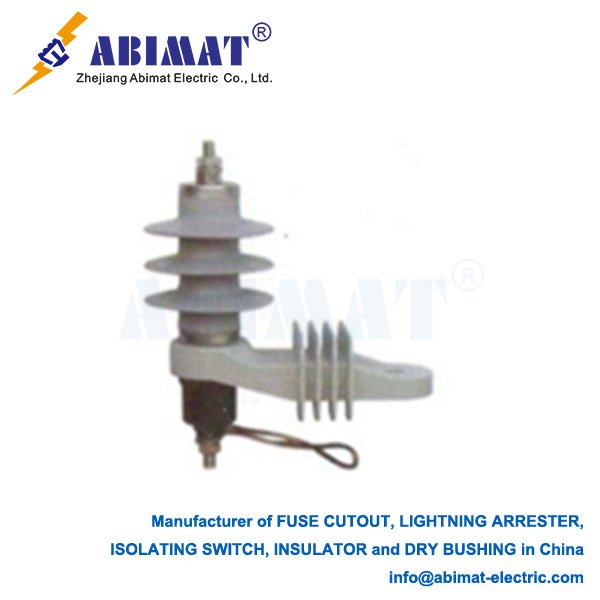
    15kV surge arresters protect electrical equipment in 15kV systems from transient overvoltages caused by lightning strikes and switching operations. They act as voltage-sensitive switches between phase conductors and ground. Under normal operating voltage (< threshold), they exhibit high impedance (open circuit). During transient overvoltages, they instantly switch to low impedance, diverting surge current to ground while clamping the voltage across protected equipment (residual voltage, Up) to a safe level below its Basic Impulse Insulation Level (BIL). Post-surge, they autonomously reset.

    Core Technology: ZnO Varistors

    Modern 15kV arresters exclusively use Zinc Oxide (ZnO) varistors. A stack of sintered ZnO discs (doped with Bi₂O₃, Sb₂O₃, etc.) forms millions of grain-boundary p-n junctions:  

      – Normal Operation: Junctions act as barriers, permitting only microamp leakage current.  

      – Surge Condition: High electric fields cause junction breakdown via quantum tunneling, enabling massive current flow to ground while clamping voltage.  

      – Self-Restoring: Junctions reform post-surge.  


    Advantages over legacy SiC technology:  

      – Lower protective levels (Up)  

      – Nanosecond response  

      – Higher energy absorption  

      – Negligible power-frequency follow current  

      – No series gaps required  

    Critical Selection Parameters

      I.Rated Voltage (Ur): Max temporary power-frequency overvoltage (RMS) withstandable for 10s (per IEC/IEEE). Must exceed site-specific Temporary Overvoltage (TOV). Typical range: 18kV–27kV (depends on system grounding).  

      II.MCOV (Max Continuous Operating Voltage): Highest RMS phase-ground voltage for continuous service. For solidly grounded 15kV systems (V_phase-ground ≈ 8.66kV), 10.2kV–13kV is typical. Critical for resistance-grounded systems.  

      III. Nominal Discharge Current (In): Peak 8/20 µs lightning current rating (e.g., 10kA or 20kA). Higher In = greater robustness for high-exposure areas.  

      IV.Protective Levels:  

        – Lightning Impulse (LPL/Up): Max residual voltage at 8/20 µs current (e.g., Up(10kA)). Must be 20-30% below equipment BIL (e.g., 95kV BIL).  

        – Switching Impulse (SPL): Residual voltage under switching surge currents (e.g., 30/60 µs).  

      V.Pressure Relief Rating: Max fault current (kA RMS) the arrester can safely interrupt if catastrophically failed. Critical for personnel safety.  

      VI.Creepage Distance: Leakage path length on housing, sized per pollution severity (IEC 60815).  

    Applications

    Deployed at critical 15kV system points:  

      – Transformer HV bushings  

      – Switchgear/Circuit Breakers  

      – Motor/Generator terminals  

      – Capacitor bank terminals  

      – Cable terminations & substation entrances  

      – Industrial/mining power feeds  

    Selection & Installation

    Selection requires:  

      – Precise matching of Ur and MCOV to system grounding and max TOV.  

      – Up must coordinate with protected equipment BIL.  

      – In and energy class must suit location exposure.  

      – Housing material (polymer/porcelain) and creepage must match pollution/altitude.  

    Manufacturers like ABIMAT provide application guides for optimal selection.  


    Monitoring & Maintenance  

    While maintenance-free, proactive measures ensure reliability:  

      – Visual inspections: Check for cracks, pollution, or leakage indicators.  

      – Leakage current monitoring: Detects ZnO block degradation (rising resistive current).  

      – Surge counters: Track arrester activity.  

      – Thermal imaging: Identifies abnormal heating.  

    Replace degraded units promptly.  

    Conclusion:

    15kV ABIMAT surge arresters, leveraging ZnO varistor technology, are indispensable for safeguarding medium-voltage equipment against transient overvoltages. Correct selection—focusing on Ur, MCOV, Up, and safety ratings—combined with basic monitoring, ensures system reliability and longevity in industrial, utility, and legacy 15kV networks.  

  • 132kV Lightning Arresters: Safeguarding High-Voltage Transmission Infrastructure

    132kV Lightning Arresters: Safeguarding High-Voltage Transmission Infrastructure

    Fuse Link Cut-Outs: The Workhorse of Overhead Distribution Protection

    Introduction

    Fuse link cut-outs are indispensable, robust, and cost-effective protective devices in overhead electrical distribution systems (typically up to 38 kV). Often called “distribution cutouts” or simply “fuse cutouts,” they serve two critical functions: providing reliable overcurrent protection for key assets like transformers and feeders, and acting as a visible, manual disconnecting point for safe circuit isolation during maintenance. Their enduring presence highlights their fundamental value in utility infrastructure.

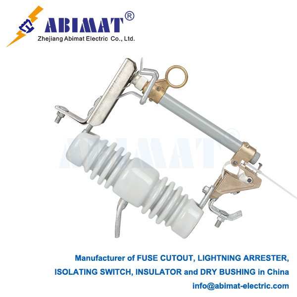
    HRW12-24F load break fuse cutout detail 1 - ABIMAT ELECTRIC

    Core Function: Precision Interruption

    The primary function of a fuse link cut-out is precise: to detect and safely interrupt excessive current flow caused by faults (short circuits or damaging overloads) within its protective zone. This action is vital for:

    I. Asset Protection: Shielding downstream equipment, especially distribution transformers, from catastrophic thermal and mechanical damage due to fault currents.

    II. System Integrity: Preventing fault currents from propagating upstream, minimizing outage scope, enhancing overall network reliability, and speeding fault location.

    III. Safety: Providing a definitive, visible break for line crew safety during work.

    Operating Principle: Controlled Arc Energy

    Interruption relies on the physics of the fusible element and its environment:

    I. Normal Load: Current flows unimpeded through the intact fusible element within its rated capacity.

    II. Fault Detection: Current exceeding the element’s calibrated rating for a specific duration (defined by its Time-Current Characteristic – TCC) causes rapid Joule heating.

    III. Element Melting: The fusible element melts (“blows”) at its weakest point, initiating an electric arc.

    IV.Arc Management & Extinction: The arc forms inside the insulating fuse tube, lined with gas-generating material (e.g., fiberglass, boric acid). Intense arc heat decomposes this lining, producing high-pressure gases expelled forcefully through designed vents. This expulsion:

           Elongates and cools the arc plasma.

           Deionizes the arc path.

           Extinguishes the arc and interrupts the fault current.

           Creates a characteristic audible expulsion (“bang”).

    V.Visual Indication & Isolation: After operation, the fuse holder assembly typically pivots downward (“drop-out” design) or displays a clear external indicator (e.g., melted target). This provides instant visual fault confirmation and establishes a safe, visible air gap isolating the downstream circuit—a crucial safety feature.

    Key Components & Construction

    A cut-out is a robust assembly comprising:


    I. Fuse Holder (Tube): The core insulating body (porcelain or modern polymer) housing the fuse link. Designed to contain arc energy, withstand weather, and channel expulsion gases downward or away safely.

    II. Removable Fuse Link: The replaceable core of the device:

           Fusible Element: Precisely calibrated wire/strip (Ag, Sn, Cu alloys) with a specific TCC for coordination.

           Arc-Quenching Lining: Surrounds the element, generating extinguishing gases.

           Strain Assembly: Maintains mechanical tension for reliable drop-out operation.

           Terminals: Ensure secure electrical contact within the cutout body.

    III. Cutout Body: The base assembly fixed to the pole or crossarm:

           Insulating Support: Provides electrical isolation and mechanical strength.

           Upper & Lower Contacts: Securely clamp the fuse holder terminals.

           Hinge & Latch: Allows the holder to pivot open after fuse operation and enables easy link replacement.

    IV. Mounting Insulator: Provides primary structural support and creepage distance.

    Primary Applications

    Fuse link cut-outs are ubiquitous for:

       Transformer Primary Protection: The dominant solution for protecting pole-mount and pad-mount distribution transformers.

       Feeder & Lateral Protection: Safeguarding main distribution feeders and branch circuits.

       Sectionalizing: Dividing feeders into protected zones to limit outage impact and aid fault location/isolation.

       Capacitor Bank Protection: Isolating faulted switched capacitor banks.

       Tap Protection: Protecting circuits branching off main feeders.

    Advantages: Simplicity and Effectiveness

    Their enduring popularity stems from key benefits:

       High Fault Interrupting Rating: Capable of clearing the high fault currents common on utility distribution systems.

       Proven Reliability & Robustness: Simple, mechanical design validated over decades under harsh conditions.

       Unambiguous Visual Indication: Instant operation confirmation (dropped holder/indicator) speeds fault finding.

       Definitive Isolation: Creates a visible, safe air gap—essential for lockout/tagout (LOTO) procedures.

       Cost-Effectiveness: Lower initial and maintenance cost than automated reclosers for many applications.

       Rapid Service Restoration: Line crews can quickly replace a blown fuse link.

    Critical Application Considerations

    Effective use requires attention to:

       Single-Interruption Device: Requires manual replacement after operation; unsuitable for temporary faults where autoreclosing is beneficial.

       Protection Coordination: Meticulously select fuse link ratings and TCCs for selective coordination with upstream devices (reclosers, substation breakers) and downstream fuses/equipment, using coordination curves.

       Environmental Impact: Ambient temperature significantly affects TCC (requiring correction factors). Wind, pollution, and altitude can influence performance and insulation.

       Expulsion Characteristics: Requires adequate vertical and horizontal clearance for safe gas venting. Not suitable for indoor or confined spaces.

       Mounting & Maintenance: Proper installation angle and periodic inspection/cleaning of insulators are vital for reliability.

    Conclusion

    The ABIMAT fuse link cut-out remains a cornerstone of safe, reliable overhead electrical distribution. Its robust construction, effective arc interruption, clear visual status, and safe isolation capability ensure its continued relevance. Despite protection technology advancements, its simplicity, cost-effectiveness, and proven performance make it the preferred choice for transformer protection and feeder sectionalizing. A thorough understanding of its operating principles, application nuances, and coordination requirements is fundamental for distribution engineers and technicians designing, operating, and maintaining resilient power networks. It stands as a testament to enduring, practical engineering.

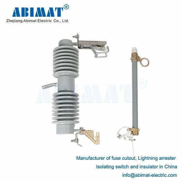
    HRW12-15kV silicone fuse cutout ABFCO123 series - ABIMAT ELECTRIC
  • 132kV Lightning Arresters: Safeguarding High-Voltage Transmission Infrastructure

    132kV Lightning Arresters: Safeguarding High-Voltage Transmission Infrastructure

    132kV Lightning Arresters: Safeguarding High-Voltage Transmission Infrastructure

    Within high-voltage (HV) transmission networks operating at 132kV, protecting critical and expensive assets from destructive voltage surges is paramount. 132kV lightning arresters (often termed surge arresters) serve as the primary defense mechanism against transient overvoltages caused primarily by lightning strikes and switching operations. These devices are engineered to ensure system reliability, prevent equipment failure, and minimize costly downtime across vital power infrastructure.

    Core Function: The High-Voltage Guardian

    The fundamental role of a 132kV lightning arrester is to act as an ultra-fast, voltage-sensitive switch connected between the phase conductor and earth. Under normal system operating conditions (when voltage remains below a specific threshold), the arrester exhibits extremely high impedance, effectively behaving as an open circuit and allowing normal current flow unimpeded. However, upon the arrival of a steep-fronted, high-magnitude transient overvoltage – potentially reaching millions of volts – the arrester instantaneously “switches” to a state of very low impedance. This creates a preferential, low-resistance path, safely diverting the massive surge current to ground. Crucially, while conducting this current, the arrester clamps the voltage appearing across the terminals of the protected equipment (Terminal Voltage or Residual Voltage) to a predetermined safe level, significantly below the equipment’s Basic Impulse Insulation Level (BIL). Once the transient energy is dissipated and system voltage normalizes, the arrester autonomously recovers its high-impedance state.

    Technology Foundation: Advanced Metal Oxide Varistors (MOVs)

    Modern 132kV arresters rely exclusively on Zinc Oxide (ZnO) varistor technology. The core consists of a carefully engineered stack of sintered ZnO discs housed within a robust, weatherproof enclosure (typically porcelain or silicone rubber polymer). Each disc comprises ZnO grains doped with precise metal oxides (e.g., Bi₂O₃, Sb₂O₃, CoO, MnO), forming a vast matrix of p-n junctions at grain boundaries.


       Normal Operation: At voltages below the arrester’s operating threshold, the p-n junctions act as high-resistance barriers, permitting only minimal leakage current (typically microamps).

       Surge Conditions: When the voltage exceeds the threshold (due to a lightning or switching surge), the intense electric field causes rapid breakdown of the p-n junctions via quantum mechanical tunneling. This results in an extremely non-linear, dramatic decrease in resistance, enabling the surge current to flow freely to earth while clamping the voltage.

       Self-Healing: As the surge voltage decays, the junctions inherently re-establish their high-resistance barriers, restoring the arrester to its blocking state without external intervention.


    ZnO technology offers unparalleled advantages for HV applications like 132kV:

       Superior Non-linearity: Provides lower protective levels (Up) relative to system BIL.

       Nanosecond Response: Virtually instantaneous reaction to fast transients.

       High Energy Absorption: Capable of handling the immense energy associated with direct lightning strikes near HV lines/substations.

       Minimal Follow Current: Negligible power-frequency current after surge diversion, eliminating the need for series gaps.

       Stability & Longevity: Proven performance under continuous operating voltage and repeated surge stresses. Manufacturers like ABIMAT employ rigorous quality control and advanced formulations to ensure reliability at this voltage class.

    Critical Performance Parameters for 132kV Arresters

    Selection and application demand meticulous attention to key specifications defined by standards (IEC 60099-4, IEEE C62.11):


    I.Rated Voltage (Ur): The maximum permissible power-frequency voltage (RMS) the arrester can withstand across its terminals for a specified short duration (typically 10 seconds) under defined temporary overvoltage (TOV) conditions (e.g., earth faults). For a 132kV system (nominal phase-phase voltage), Ur is typically selected between 120kV and 144kV, based on system grounding (solidly grounded, resistance grounded, isolated) and expected TOV magnitude and duration. Ur MUST exceed the maximum prospective TOV.

    II.Maximum Continuous Operating Voltage (MCOV): The highest RMS power-frequency voltage (phase-to-earth) that can be continuously applied across the arrester terminals without degrading its long-term performance. For a solidly grounded 132kV system (V_phase-earth ≈ 76.2kV), an MCOV of 84kV, 90kV, or 96kV is common, providing necessary safety margin.

    III.Nominal Discharge Current (In): The peak value of the standard 8/20 µs lightning current wave used for classification and routine testing (e.g., 10kA, 20kA). Higher In ratings (e.g., 20kA) indicate greater robustness and are standard for HV transmission line and substation applications exposed to high lightning intensity.

    IV.Line Discharge Class (IEC) / Duty Cycle (IEEE): Classifies the arrester’s ability to absorb energy from line discharges following switching operations. Higher classes (e.g., Class 3,4,5) denote greater energy handling capability, critical for 132kV systems.

    V.Lightning Impulse Protective Level (LPL / Up): The maximum residual voltage measured across the arrester terminals when subjected to a standard 8/20 µs impulse current of a specific magnitude (e.g., Up(10kA), Up(20kA)). This is the critical “clamping voltage.” It must be significantly lower than the BIL of the protected equipment (e.g., 550kV or 650kV for 132kV transformers/switchgear).

    VI.Switching Impulse Protective Level (SPL): The maximum residual voltage under a standard switching surge impulse current (e.g., 30/60 µs, 45/90 µs, or 250/2500 µs wave).

    VII.Steep Current Impulse Protective Level: Residual voltage under a very fast front impulse (e.g., 1/2 µs), important for close-up strikes.

    VIII.Pressure Relief Rating: The maximum prospective symmetrical fault current (kA RMS) the arrester housing can safely withstand and interrupt in the event of an internal failure, preventing violent rupture. This is absolutely critical for personnel safety and equipment protection within HV substations. Integral disconnectors may visually indicate failure.

    IX.Creepage Distance: The leakage distance over the insulating housing surface, sized according to the specific pollution severity class (IEC 60815) of the installation site.

    Applications in 132kV Systems

    132kV lightning arresters are strategically deployed at key points:

       Transformer Protection: Directly connected to HV bushings of 132kV power transformers (primary side).

       Substation Entrances: Protecting incoming/outgoing transmission lines at the substation boundary.

       Busbar Protection: Shielding main and transfer busbars within switchyards.

       Shunt Reactor/Capacitor Bank Protection: Mitigating switching surges associated with reactive power compensation equipment.

       Cable Sealing End Protection: At transitions between overhead lines and underground cables.

       Critical Generator Step-Up (GSU) Transformer Protection: At power plant interfaces.


    Selection & Coordination


    Selection involves rigorous matching of arrester ratings (Ur, MCOV, In, Protective Levels, Energy Class) to:

       System nominal voltage (132kV) and grounding practices.

       Maximum prospective Temporary Overvoltages (TOVs).

       Lightning Exposure Level (keraunic level) and location (tower, substation).

       BIL and insulation coordination requirements of protected equipment.

       Site pollution severity and altitude (requiring creepage correction).

       Prospective short-circuit current for pressure relief rating. Coordination studies ensure the arrester provides effective protection without compromising upstream/downstream devices.


    Monitoring & Maintenance


    While designed for long, maintenance-free service, monitoring is vital:

       Visual Inspection: Regular checks for housing damage (cracks, tracking), pollution buildup, terminal corrosion, and leakage indicators.

       Leakage Current Monitoring: Online or offline measurement of resistive leakage current component can indicate early degradation of ZnO blocks.

       Surge Counters: Record the number of surge events exceeding a threshold.

       Thermal Imaging: Can detect abnormal heating due to internal degradation. Prompt replacement of suspect or failed units is essential for continued system security.

    Conclusion

    The 132kV lightning arrester, underpinned by advanced ZnO varistor technology, is an indispensable component for the security and reliability of high-voltage transmission networks. Its ability to instantaneously limit potentially catastrophic overvoltages to safe levels protects multi-million dollar equipment, ensures grid stability, and guarantees continuous power supply. Precise selection based on comprehensive system analysis, adherence to standards, and diligent monitoring – supported by quality manufacturers like ABIMAT – are fundamental for maximizing the operational lifespan and effectiveness of these critical guardians of the grid.