Author: Zhou

  • High Voltage Cutout: A Critical Overhead Line Protector​

    High Voltage Cutout: A Critical Overhead Line Protector​

    High Voltage Cutout: A Critical Overhead Line Protector​

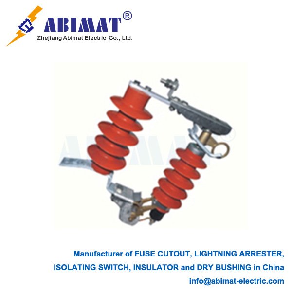
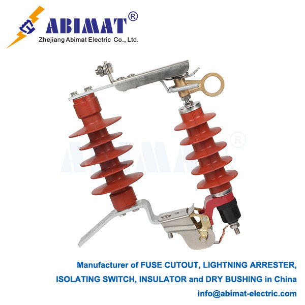
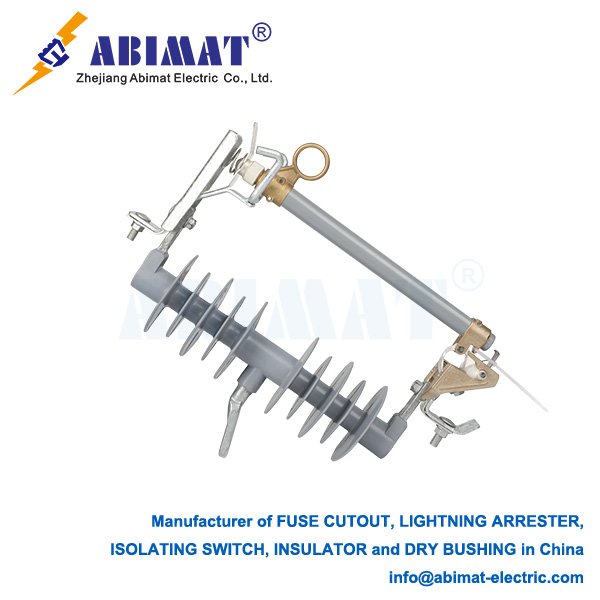
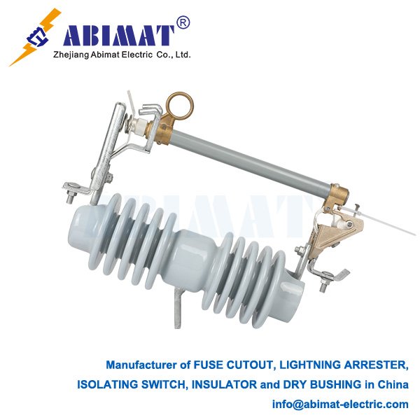
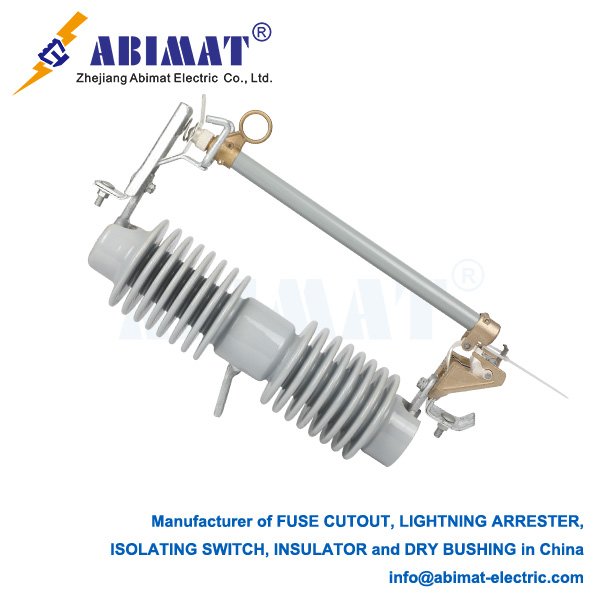
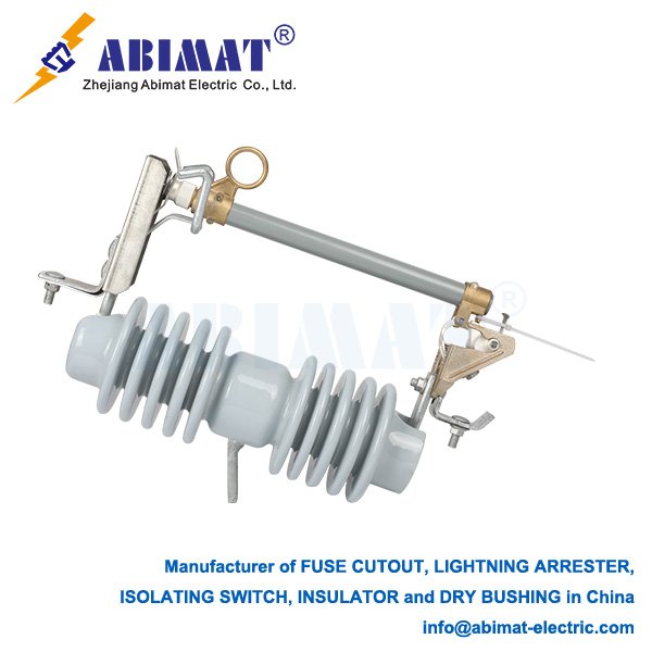
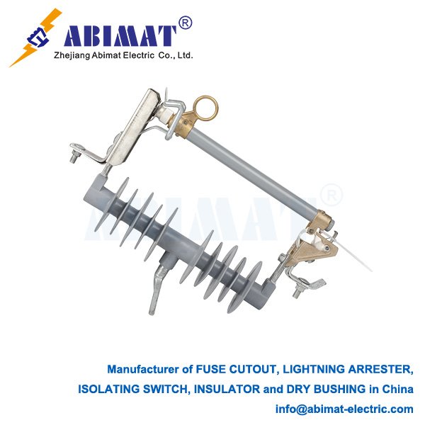
      A high voltage cutout—people often call it a fused cutout or drop-out fuse—is a basic, single-phase protective device. It’s widely used in overhead electrical distribution systems. These systems usually work at voltages between 2.4 kV and 38 kV. The cutout has two main, important jobs.​
      First, it protects against overcurrent. It acts as the main fuse for things like distribution transformers, capacitor banks, feeders, or tap lines. When there’s a lasting overcurrent—this happens from faults like short circuits or bad overloads—the fuse link inside the cutout melts, or “blows.” This melts safely stops the fault current.​
      Second, it provides a visible break in the circuit. When the fuse works, or when someone uses a hot-stick to operate it by hand, the fuse holder (or “door”) swings down into an “open” position. This position clearly shows the circuit has no power downstream. It also lets workers safely isolate the area for maintenance or repair.​
      Let’s look at its key parts and how it works. The insulator is one part. It holds the cutout up and keeps live parts separate from the grounded mounting bracket—this bracket is usually attached to a utility pole’s crossarm. Insulators are made of strong polymer or porcelain.​
      The fuse holder (also called carrier or door) is another part. It’s a conductive tube that moves. It holds the fuse link and connects the upper contact (linked to the line) and lower contact (linked to the load side, like a transformer).​
      The fuse link is a replaceable part inside the holder. It has a calibrated fusible element—often silver or tin-coated copper wire. This element sits in arc-quenching material, like boric acid and silica sand. When overcurrent lasts, the element melts. The arc from this melts the quenching material, making gases that quickly put out the arc.
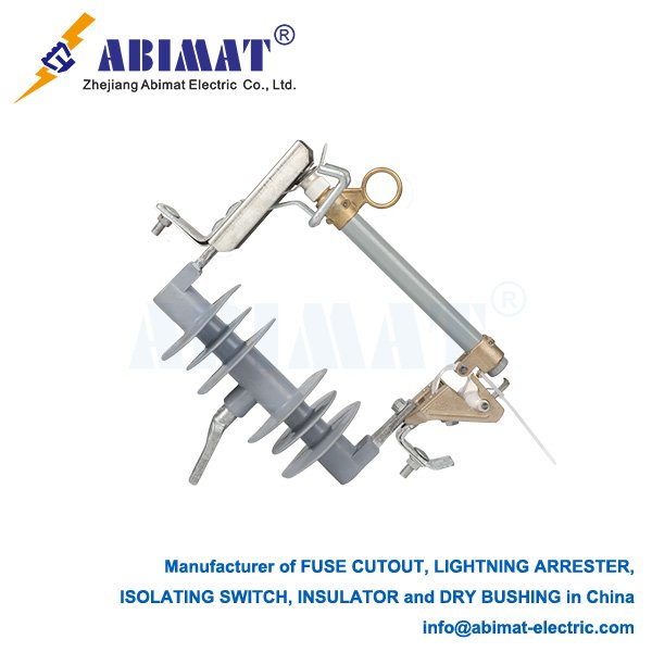
      The cutout also has mounting and contacts. The whole assembly is firmly attached with a bracket. Upper and lower contacts are the points where electricity connects.
      High voltage cutouts are essential for many reasons. They only isolate the faulty part, so outages don’t affect too much. They keep workers safe by showing an open point and letting people ground the isolated section. They’re also cheap and simple—more so than circuit breakers for many distribution uses. And they’re reliable, with high interrupting ratings (usually 10kA symmetrical or higher).
      You’ll mostly find them protecting distribution transformers and capacitors. They also help section off overhead feeders, so faults are isolated and the system works better.
      In short, the  abimat high voltage cutout is a device you can’t do without in overhead power distribution. It combines reliable overcurrent protection (from the fuse) and clear visible isolation. This makes it a key part of safe and efficient grid operation.
  • Disconnecting Switch (20 kV): Essential Components for Medium-Voltage Safety

    Disconnecting Switch (20 kV): Essential Components for Medium-Voltage Safety

    Disconnecting Switch (20 kV): Essential Components for Medium-Voltage Safety

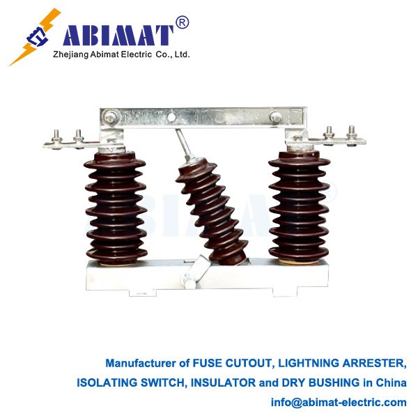
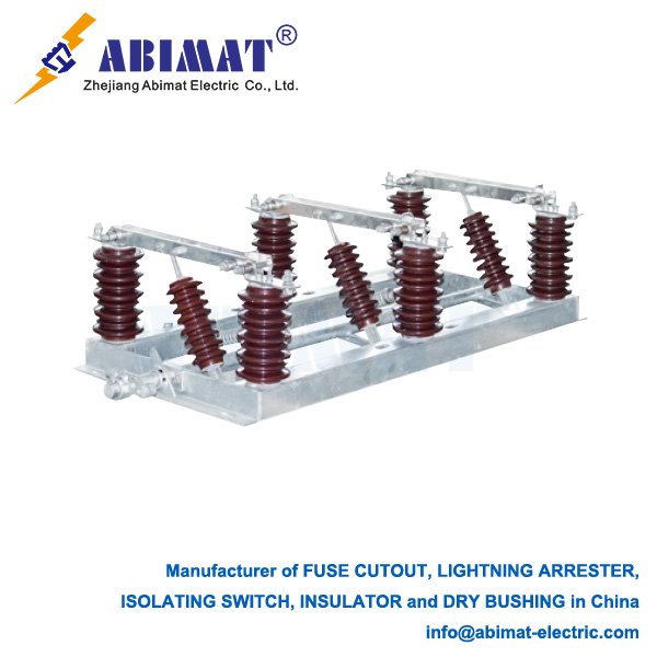
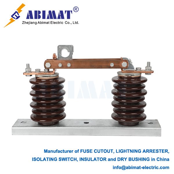
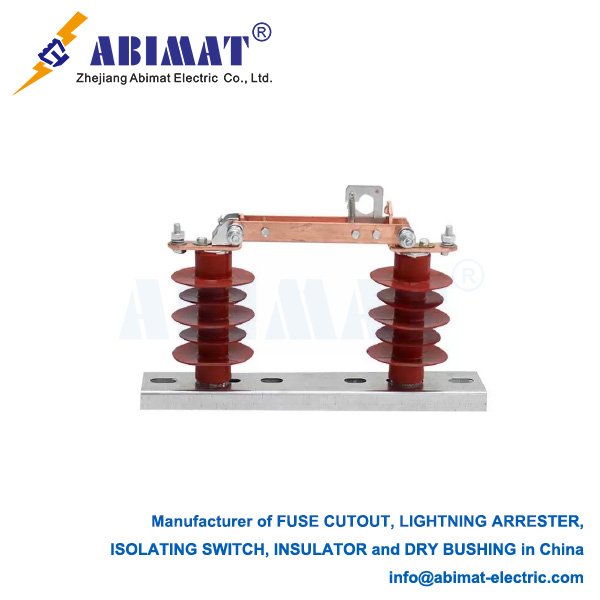
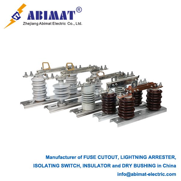
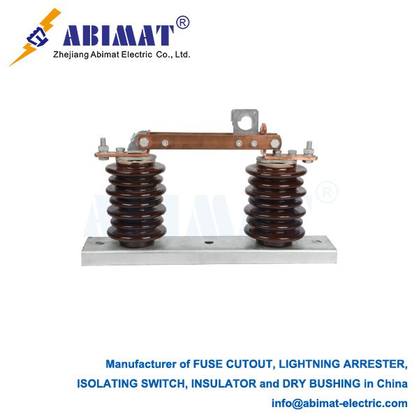
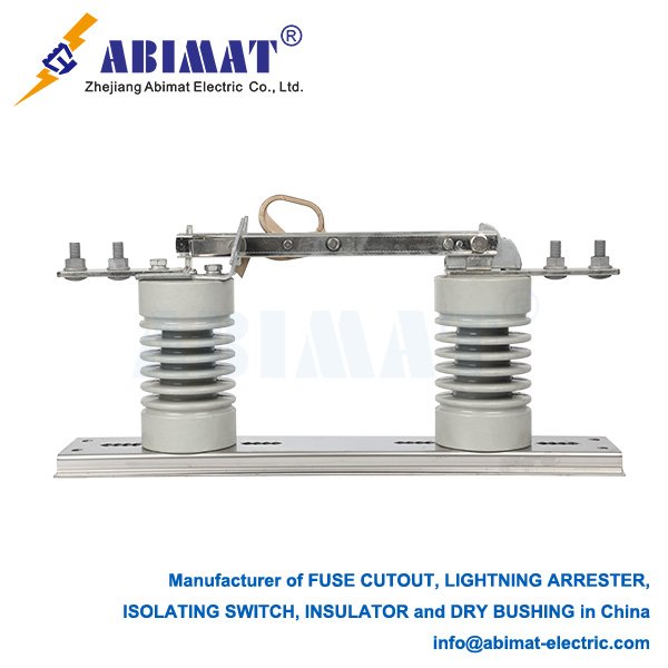
    A 20 kV disconnecting switch—also called an isolator—is a key safety device in medium-voltage power systems. Its main job is to make a physical break in the circuit during maintenance. This break is a visible air gap over 150mm wide, helping workers check the circuit has no power.

    The switch also stops the circuit from getting power by accident. It uses mechanical or electrical links to circuit breakers, and these links follow the “five prevention” rules. One rule, for example, stops it from switching loads.

    Remember: this switch can’t stop electric arcs. So never use it to switch loads. When you use it, follow this order: the circuit breaker opens first, then you use the isolator—only after the current hits zero.

    For structural design, the contact system has main contacts with silver-plated surfaces. The silver layer is at least 20 μm thick, and surface hardness is at least 120 HV. This coating keeps resistance low and stops oxidation. Finger contacts use spring pressure for stable point contact.

    Insulation: air is the usual type, but some switches use SF₆ gas for polluted areas. The switch’s dielectric strength must handle 42 kV for 1 minute, following GB/T 1985.

    Mechanical assembly includes a stainless steel housing and glass-filled nylon operating mechanisms. Outdoor switches have an IP65 rating, resisting corrosion and dust.

    Key technical rules: system max rated voltage over 20 kV (per GB/T 1985, IEC 60947-3); handles 31.5 kA for 4 seconds (tested via dynamic stability); insulation resistance ≥1000 MΩ (tested with 500 V DC); mechanical life 10,000 cycles (M2 grade, needs regular lubrication); contact resistance ≤50 μΩ (checked with a micro-ohmmeter).

    Safety and maintenance rules: before switching, check the breaker’s status and confirm no voltage with testers. Test once a year—include thermal imaging (temp rise ≤65 K at 1.05× rated current) and insulation resistance checks. Wrong use causes bad arcs, like a 2019 15 kV incident that broke equipment. Newer designs have triple interlocks (mechanical, electrical, software).

    Conclusion:

    The abimat 20 kV switch is a must for safe medium-voltage grid work. Follow IEC/GB standards, do careful maintenance, and use smart sensors (for real-time temp/vibration checks) to boost reliability. Following operation rules is key to stop big failures.

  • Hollow Insulators: Critical Components for High-Voltage Systems

    Hollow Insulators: Critical Components for High-Voltage Systems

    Hollow Insulators: Critical Components for High-Voltage Systems

    Introduction

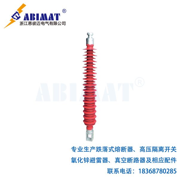
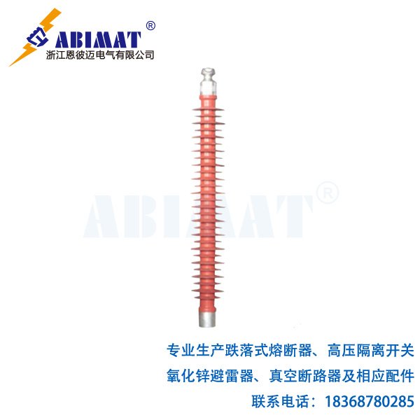
    Hollow insulators are basic parts in many places. In Gas Insulated Switchgear (GIS), they make the grounded cases. They also keep different phases and sections insulated from each other. In dead tank circuit breakers, they hold the interrupter units and contain the insulating gas. For surge arresters, they hold the active parts inside. In instrument transformers (current and voltage types), they separate the primary conductor and act as the insulating cover. For bushings, they guide high-voltage conductors through grounded walls or tanks—like those on transformers, circuit breakers, and capacitors. In disconnectors and earthing switches, they support moving contacts and provide insulation. They are also used in Capacitor Voltage Transformers (CVTs).

    Structure and Materials

    Their core structure is what makes them different—it’s usually a cylinder. This core is sealed at both ends with metal plates or end parts. This creates a container that can hold insulating materials, like sulfur hexafluoride (SF6) or oil. Sometimes it just separates a conductor.

    The outer shell gives the main electrical insulation. There are two main materials for this shell. One is composite, or polymer. It has a fiberglass-reinforced epoxy (FRP) tube for mechanical strength. Around this tube, there are silicone rubber covers and sheds. Silicone repels water well, works great in dirty conditions, is light, and resists impacts. This is the most common type used today. The other material is porcelain, or ceramic. It’s a traditional material that’s strong when pressed and stays stable for a long time. It needs a glaze to repel water, though. It’s heavier, easier to break, and doesn’t work as well in dirty conditions as composite insulators.

    Key Functions and Advantages

    For electricity, they provide the insulation needed. They keep the right distance between the high-voltage conductor inside and the grounded structure outside. This stops electrical flashes. They also work as strong structural parts. They support heavy components—things like circuit-breaker interrupters, disconnector contacts, transformers, capacitors, or busbars. Often, these parts have big cantilever loads. They form a sealed space too. This space holds insulating or arc-quenching materials (like SF6, oil, or air) at working pressures. This is very important for Gas Insulated Switchgear (GIS), dead tank circuit breakers, instrument transformers, and bushings. They also act as a barrier against the environment. They protect inner parts from outside dirt, like moisture, dust, and pollution. On the flip side, they keep inner materials safe inside.

    Composite hollow insulators are getting more popular for good reasons. They are lighter—this makes them easier to handle and reduces loads on structures. They resist damage from vandalism and don’t shatter explosively. They work well in dirty and humid places because they repel water. And they usually need less maintenance.

    Primary Applications

    Hollow insulators are basic parts in many places. In Gas Insulated Switchgear (GIS), they make the grounded cases. They also keep different phases and sections insulated from each other. In dead tank circuit breakers, they hold the interrupter units and contain the insulating gas. For surge arresters, they hold the active parts inside. In instrument transformers (current and voltage types), they separate the primary conductor and act as the insulating cover. For bushings, they guide high-voltage conductors through grounded walls or tanks—like those on transformers, circuit breakers, and capacitors. In disconnectors and earthing switches, they support moving contacts and provide insulation. They are also used in Capacitor Voltage Transformers (CVTs).

    Conclusion

    The abimat hollow insulators are smart, multi-use parts. They are critical for safe, reliable, and smaller designs of modern high-voltage electrical equipment. More and more people are using composite technology. This has made their performance much better, especially in hard environments. It also brings benefits in weight, safety, and lifecycle costs. They can do three things at once: insulate electricity, give mechanical strength, and hold pressure. This makes them a must-have for uses from substations to transmission systems. Factories follow strict global rules (like IEC, IEEE, ANSI) when designing, testing, and making them. This ensures they are reliable.

  • Essential Components of a Modern Lightning Arrester

    Essential Components of a Modern Lightning Arrester

    Essential Components of a Modern Lightning Arrester

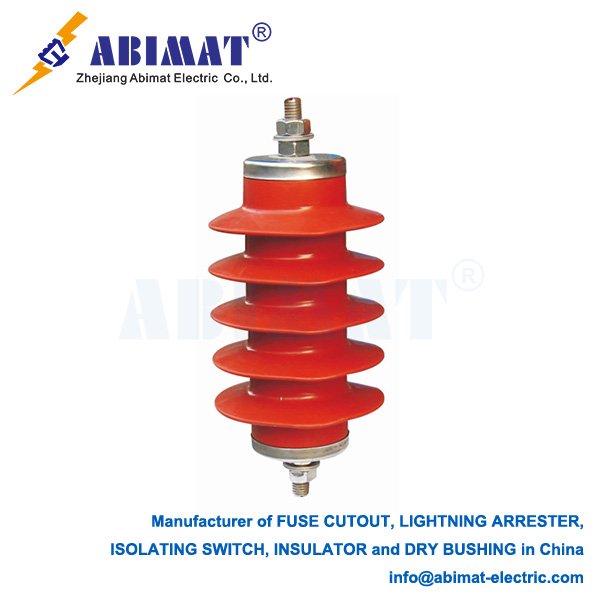
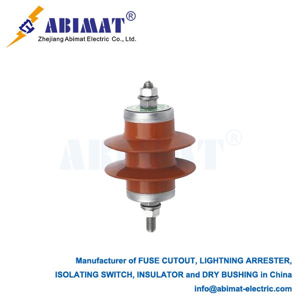
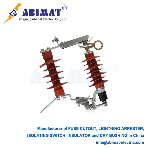
    Lightning arresters, or surge arresters, protect electrical equipment from harmful voltage surges. These surges come from lightning or switching operations. Knowing their key parts helps in choosing, using, and maintaining them right. Modern high-voltage arresters use Zinc Oxide (ZnO) technology. They have several basic components.

    The Metal Oxide Varistor (MOV) Blocks are the core. These are ceramic blocks made mainly of zinc oxide grains. They also have small amounts of other metal oxides like Bi2O3, Sb2O3, CoO, MnO. Their voltage and current relationship is highly nonlinear. At normal system voltage, they have high resistance. Only a tiny current, in microamps, leaks through. When a surge above their reference voltage hits, their resistance drops fast—within nanoseconds. This lets the big surge current go safely to the ground. Once the surge ends, they quickly go back to high resistance. This stops power from flowing through. To get the right voltage rating and energy handling, these blocks are stacked in series or parallel inside the housing.

    The Housing, or Enclosure, has many roles. It supports the arrester mechanically. It protects the inside from moisture, pollution, and UV rays. It also insulates the internal MOV column. Different materials are used. Porcelain is traditional. It is strong. Its hydrophobic glazing helps with pollution. But it is heavier and more likely to break than polymer. Polymer, like Silicone Rubber or EPDM, is getting more popular. It repels water well. It is lighter. It can take more impact without shattering. It works better in dirty places. The housing has sheds, which are ribs. These increase the creepage distance, improving pollution handling.

    End Fittings, or Terminals, are where electricity connects. They link the internal MOV column to the outside system—the line terminal—and to the ground, the ground terminal. They also help seal the housing tightly. They are usually made of corrosion-resistant aluminum or copper alloy. The line-end fitting connects to the high-voltage wire. The ground-end fitting connects to the grounding system. They have strong parts for connecting wires, like lugs or bolted pads.

    The Sealing System makes a tight seal between the housing and end fittings. It keeps moisture and dirt out. If these get in, they can damage the MOV blocks or cause internal flashovers. A bad seal often leads to arrester breakdown or failure. To keep the seal good for long, special rubber gaskets like O-rings, compression fittings, and sometimes epoxy or glass-to-metal seals are used.

    The Internal Structure and Compression System holds the MOV column firmly inside the housing with controlled pressure. The right compression is important. It keeps the blocks in good electrical contact. It also ensures they share voltage and current evenly when working. Springs or rubber pads are often used. They keep pressure steady even when temperatures change.

    Grading Rings are optional but common for high or extra high voltage arresters. They go around the line-end of the housing, especially for higher voltages. They control the electric field along the arrester. This stops too much voltage stress where the line-end terminal meets the housing. It also spreads voltage more evenly across the internal MOV blocks. This helps the arrester stay stable and last longer.

    Mounting Brackets or a Base let the arrester attach securely to a support structure. This could be a pole, tower, pedestal, or substation frame. They need to handle forces like wind or earthquakes. They also make sure there is enough space between things. Grounding connections usually go through the base or directly to the ground terminal.

    A  ABIMAT modern lightning arrester’s performance and reliability depend much on each part’s design, material quality, and careful making. The nonlinear ZnO MOV blocks, protective housing, strong sealing system, and good electrical and mechanical connections work together. This teamwork lets the arrester handle system voltage stress repeatedly. It also lets it safely redirect harmful surge energy. Knowing these parts is key for engineers who choose, install, and maintain these important protectors.

  • 150 kV Disconnecting Switches: Critical Components for High-Voltage Safety

    150 kV Disconnecting Switches: Critical Components for High-Voltage Safety

    150 kV Disconnecting Switches: Critical Components for High-Voltage Safety

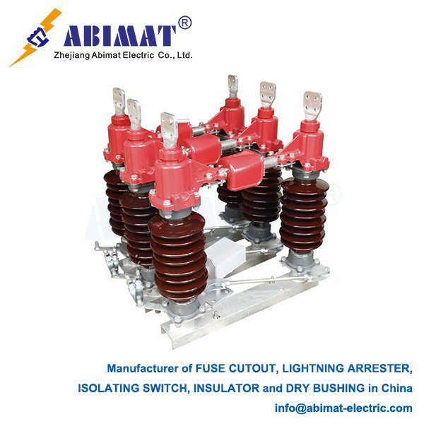
    A 150 kV disconnecting switch—also called an isolation switch—is a basic safety device in high-voltage electrical networks. Its main job is to make a clear, physical gap in circuits that have no power. This gap keeps things safe when people do maintenance or repairs. It can’t stop electric arcs, though. You have to use it only after the upstream circuit breakers have turned off the load current in the circuit.

    Visible isolation is a big part of how it works. It gives a clear visual sign that the circuit is disconnected. This is more important for safety than just using electrical indicators. The switch has a contact setup with two breaks per phase. These two gaps in a row make the dielectric strength much better than switches with just one break. That’s good for reliability at 150 kV.

    It uses strong motorized drives—usually brushless DC motors—to move. These drives have closed-loop control for position and speed. This precise control stops the switch from being only partly engaged, which would be unsafe. It also makes sure the switch works the same way no matter the environment. For insulation, it uses high-strength polymer composite or porcelain insulators. These are made specifically to handle 150 kV, including the system voltage and sudden high-voltage spikes.

    Electrical integrity is key for safety and performance. The switch is built to handle standard power frequency voltages—like 275 kV AC—and lightning impulse voltages, such as 650 kV BIL, following IEC 62271-102. It keeps its insulation working even when there’s a transient recovery voltage (TRV).

    Interlocking systems are a must. They connect mechanically or electrically with the related circuit breakers. This stops the switch from being used when there’s a load, which could cause a terrible failure.

    Environmental protection matters too. Mechanical parts are made of alloys that resist corrosion. Composite insulators have hydrophobic silicone rubber coatings. These features stop pollution, salt fog, or industrial contaminants from making the switch work worse. The switch is also built to last, with a mechanical life of at least 10,000 operations under rated conditions. That means it can be reliable for a long time.

    150 kV disconnecting switches are essential in substations. They isolate transformers, bus sections, feeders, and transmission lines. You’ll also find them in renewable energy places—like solar farms and wind parks. There, they isolate DC arrays and connect to the grid.

    Modern switches have digital signal processor (DSP) control systems. These systems watch the blade position, motor torque, and operating speed in real time. This helps with predictive maintenance and finding problems, like jamming or the switch not closing all the way.

    New ideas are coming in, too. People are adding IoT sensors to check the switch’s condition all the time—things like contact resistance and how dirty the insulators are. They’re also trying hybrid designs with solid-state parts. These could work for special cases where you need to interrupt without an arc.

    Design, testing, and certification follow strict international standards. IEC 62271-102 sets rules for requirements, dielectric testing, mechanical endurance, and temperature rise tests. ANSI/IEEE C37.32 has American standards for ratings, construction, and testing. Independent groups like KEMA or UL check that the switches meet these standards and are safe.

    Disconnecting switches only work as isolation devices. You have to follow strict steps to use them. First, turn off the circuit with the upstream circuit breaker. Then, check that there’s no voltage. Next, move the disconnecting switch to the open position. Finally, put on lockout/tagout (LOTO) safety devices.

  • Composite Type Insulators: Enhancing Electrical Grid Reliability

    Composite Type Insulators: Enhancing Electrical Grid Reliability

    Composite Type Insulators: Enhancing Electrical Grid Reliability

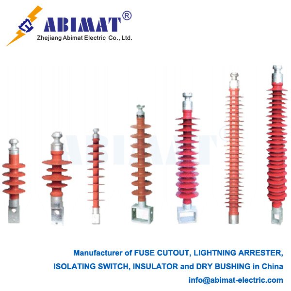
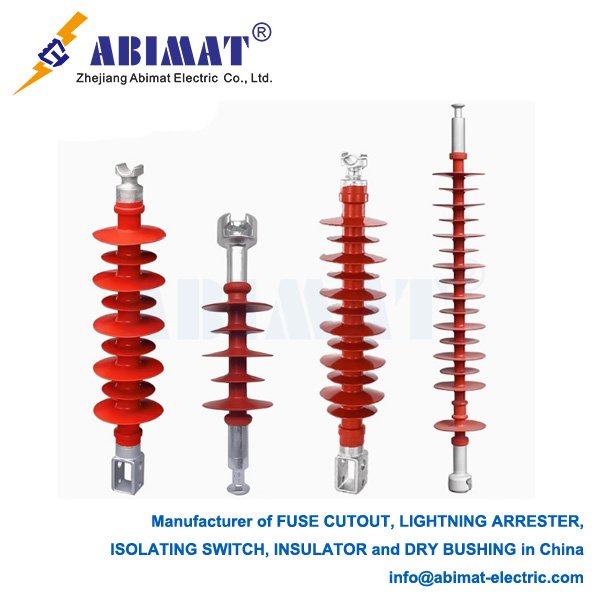
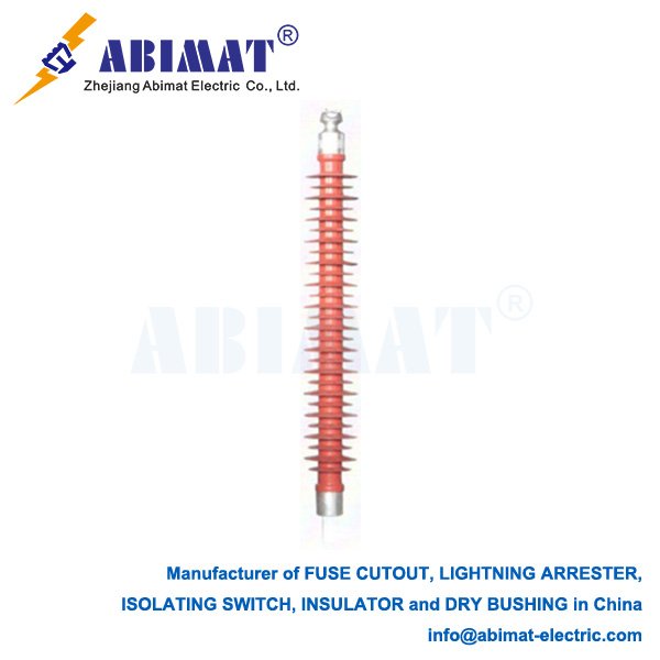
    Composite insulators, also called polymer or non-ceramic insulators (NCIs), are a big step forward in high-voltage electrical insulation. They have two main parts. One is a strong fiberglass-reinforced polymer (FRP) core rod that holds weight. The other is an outer cover with polymeric weather sheds. These sheds are usually made from silicone rubber (SIR), ethylene propylene diene monomer (EPDM), or cycloaliphatic epoxy (CEP).

    The FRP core is key here. It has great tensile strength. That means it can handle mechanical loads—like the weight of conductors, wind, and ice. It also has high dielectric strength. Unlike brittle materials, it doesn’t break easily. And it’s much lighter—about 80-90% lighter than similar porcelain or glass insulators. This light weight makes it more durable and easier to install.

    The outer cover, mostly made of silicone rubber, has important features too. Silicone rubber naturally keeps water away. That stops a uniform conductive water film from forming on the surface. Even after pollution, this water-repelling property often comes back. It can even transfer to pollutants. This is a big deal. It cuts down on leakage currents a lot. It also stops pollution flashover—a common problem for ceramic insulators in dirty or coastal areas.

    Being lightweight helps in other ways. It makes handling, transporting, and installing the insulators simpler. That lowers costs for labor and structural support. Composites are tough against impacts and vandalism too. Unlike brittle ceramics, they don’t shatter if shot or hit. This makes the power grid more resilient.

    They work well in polluted places. The water-repelling feature, along with good leakage distance designs, lets them operate reliably in heavy industrial areas, deserts, or coastal regions. Good manufacturing is important here. It ensures a tight seal between the core and the cover. That keeps moisture out and prevents core corrosion—something that could make them fail.

    Composite insulators are now used all over the world in electrical networks. They’re in suspension strings for overhead transmission and distribution lines. They’re in line post setups in distribution systems. They’re used as station post insulators in substations. They insulate apparatus like circuit breakers and transformers. They’re in dead-end and tension applications. And they’re part of high-voltage direct current (HVDC) systems.

    But there are things to watch for with their long-term performance. Core brittle fracture is one. If moisture gets through a bad end-seal, it can cause acid to break down the glass fibers in the FRP core. To stop this, manufacturers need strict quality control.

    Tracking and erosion can happen too. If the insulators are under electrical stress for a long time, and with environmental factors, the surface of the cover might degrade. But new silicone rubber formulas are much better at resisting this.

    Polymer covers have UV stabilizers. Silicone rubber, in particular, holds up well against weathering from UV rays. Sometimes, animals can be a problem. In certain designs or locations, steps need to be taken to stop damage from birds or other wildlife.

    Research is ongoing to improve the materials. Scientists are looking at nano-filled silicones. These could make the insulators more resistant to erosion and better at handling heat. They’re also working on better ways to check the insulators’ condition—like analyzing leakage currents or detecting acoustic emissions. There are designs being optimized for ultra-high voltage (UHV) systems and very harsh environments.

    Abimat composite type insulators have changed electrical insulation. They work better in polluted conditions. They’re strong mechanically, light, and hard to vandalize. All this means big benefits—both operational and economic—compared to traditional ceramic insulators. Materials, manufacturing, and design keep getting better. This ensures they’ll be key parts of building reliable, efficient, and modern electrical infrastructure. They’re especially useful in tough operating conditions. To make them last as long as possible, keeping strict quality standards and understanding how they age over time is crucial.

  • Composite Pin Insulators for Overhead Distribution Systems​

    Composite Pin Insulators for Overhead Distribution Systems​

    Composite Pin Insulators for Overhead Distribution Systems​

    Composite pin insulators play a key role in modern overhead power lines. They take the place of old porcelain units with advanced polymer designs. They work better in harsh environments. They also cut down on maintenance costs.

    These insulators have three connected layers. The fiberglass epoxy rod is the core that bears the load. It has a tensile strength over 100 kN. It resists breaking suddenly. The silicone rubber housing acts as a weather-resistant cover. It repels water, which helps it shed dirt and grime. The metal end fittings are forged steel caps. They are crimped to the rod with more than 120 tons of pressure. They are sealed to keep moisture from getting in.

    They have several big performance advantages. They are light—only 2–4 kg. Porcelain ones weigh 8–12 kg. This light weight cuts installation time by 40%. It also means the poles do not need to be as strong. They handle pollution well. In coastal or salt-fog areas, they keep a Basic Impulse Level over 150 kV. That is twice what porcelain can do. They stand up to vandalism. The elastic housing can take gunshot impacts. It passes IEC 62217 ballistic tests. They help stop flashovers. Their ability to repel water keeps leakage current below 5 mA at 15 kV, even when very dirty.

    They have standard voltage ratings. For distribution, these are 15–36 kV. They follow ANSI 55-5 and 55-6. They can handle strong mechanical loads—at least 12,000 lb. They meet ANSI Class 55-5 minimum failing load. The creepage distance is 432–890 mm. It depends on the pollution level, following IEC 60815. They work in a wide range of temperatures—from -50°C to +80°C. They do not get brittle.

    Rigorous testing shows they are good quality. They stay stable under UV light. After 5,000 hours of accelerated weathering (following ASTM G154), their hardness changes by less than 5%. Their seals hold up. They pass a 96-hour boiling water test without losing dielectric strength. The end fittings resist rust. They survive 1,000 hours of salt-spray exposure, as per ASTM B117. They also last electrically. They handle 100,000 flashover cycles at 1.2× rated voltage.

    Field failure rates are under 3%. Most failures come from a few problems. One is rod brittleness. Acid-resistant glass fibers (with pH over 4.5) fix this. Interface erosion is controlled with triple-sealing: an EPDM gasket, mastic, and overmold. UV damage is reduced by ATH-filled silicone rubber.

    Torque limits are important. For 15 kV class, 35–45 N·m stops the core from cracking. In polluted areas, position them at a 15°–30° angle. This helps them clean themselves when very dirty. For checking damage, annual drone checks find cracked sheds or corona rings.

    Abimat Composite Pin Insulators meet ANSI C29.16, IEC 61952, and IEEE 1523 standards. They last over 40 years. Porcelain ones last 25 years. Regular washing helps. Now, 75% of new North American distribution lines use composite pin insulators. They are tough, need less maintenance, and save 30–50% in lifecycle costs compared to porcelain.


  • Fuse Cutout Open Operation in Overhead Distribution Systems

    Fuse Cutout Open Operation in Overhead Distribution Systems

    Fuse Cutout Open Operation in Overhead Distribution Systems

    A fuse cutout—also called a fused cutout or drop-out fuse—is a key protective device on overhead power lines. When it’s in the “open” state, it intentionally disconnects the part of the circuit with a fault. This stops equipment from getting damaged and keeps the grid stable.

    Operating Principle

    Sustained overcurrent flows through the fuse holder—usually from faults like downed conductors or transformer failures. The fusible element inside heats up fast. This element, made of carefully calibrated tin or silver alloy, melts when the current and time hit a set limit.

    Once it melts, gravity makes the fuse tube pivot down (“drop out”). This creates a visible air gap. The open position cuts off the electricity and acts as a clear sign of a fault for line crews.

    Key Design Features

    Standard units have voltage ratings from 15 kV to 38 kV for distribution systems, with 27 kV being the most common.

    They can interrupt current, rated for 12.5 kA symmetrical fault current as per IEEE C37.41.

    Fuse links come in T, K, or H speed types—”K-link” fuses, for example, clear faster and work well for transformer protection.

    They have good dielectric strength, withstanding 110 kV BIL (Basic Impulse Level) to resist lightning-caused flashovers.

    The fiberglass tube helps put out arcs. When melting, it makes deionizing gases that quench arcs in 1–2 cycles.


    Critical Performance Metrics

    Time-Current Characteristic (TCC) tells how fast fuses work. K-speed fuses clear 200% overloads in 10 seconds or less; T-speed ones handle inrush better, taking about 30 seconds. They must work with reclosers—fuses operate after 2–3 recloser shots, usually with a 0.5–10 second delay.  


    Mechanical endurance is strong. They pass 10,000+ load-break operations, as per IEEE C37.42. Hinges can take 500 lbf vertical tension without bending.  

    Field Applications & Safety

    For transformer protection, K-speed fuses guard against secondary faults—like 25 kAIC for 500 kVA units.  


    Sectionalizing is another use: they isolate faulted laterals, with 70% of cutouts on distribution feeders doing this job.  


    Safety margins are built in. They’re rated at twice the continuous current—say, a 100A fuse handles a 50A load.  


    Installation has rules. Keep at least 1.5 m between phase and ground, following NESC 234. Always install them to pivot downward, so they drop out reliably.

    Maintenance & Failure Modes

    Annual infrared inspections find hot spots. These come from corrosion or loose contacts.  


    Common failures happen in a few ways. False opens, for example, are caused by vibration fatigue—helical spring retainers fix this. Nuisance melting happens because of wrong TCC coordination or temporary overloads. Dielectric failure comes from tracking across dirty porcelain insulators; silicone-coated units lower this risk.

    Standards Compliance

    All designs meet IEEE standards: C37.41 for testing, C37.42 for ratings, and C37.46 for interrupting capacity. Modern cutouts with polymer housings—silicone rubber, for example—work better than porcelain in areas with lots of pollution. They cut flashovers by 40%.

    Conclusion

    Abimat fuse cutouts provide fail-safe circuit protection. They do this through deliberate mechanical disconnection. Correct TCC coordination and annual thermographic checks keep them reliable across utility distribution networks.

  • 115 kV Disconnecting Switches: Technical Specifications and Applications

    115 kV Disconnecting Switches: Technical Specifications and Applications

    115 kV Disconnecting Switches: Technical Specifications and Applications

    Disconnecting switches (isolators) serve as critical safety components in 115 kV substations and transmission networks. These devices provide visible circuit isolation for maintenance, system reconfiguration, and grounding operations. Unlike circuit breakers, disconnecting switches do not interrupt load current or fault current.

    Primary Functions

    The visible air gap creates a physical isolation space—over 1.5 m for 115 kV systems. It confirms the power is off, following IEC 62271-102 rules.

    Integrated grounding blades, whether manual or motor-run, safely release trapped electricity to the ground.

    They handle continuous current, usually 1,250–2,000 A, and short bursts too—like 40 kA RMS for 3 seconds.

    They pass standard dielectric tests: 230 kV AC for power frequency and 550 kV for lightning impulse.

    Common 115 kV Configurations

    Center-Break Horizontal Rotary (Double-Access) has rotating blades that open and close horizontally. It’s standard for bus connections needing at least 2.5 m between phases. It can handle radial ice loading of 20 mm or more, as per IEC 62271-3.

    Vertical-Break (Single-Access) uses vertically moving blades, which take up less space. It works well for linking GIS to overhead lines.

    Pantograph Type has collapsible arms, saving space. You’ll often find it in transformer bays.


    Construction Features

    The conductive path uses aluminum alloy blades with silver-plated contacts. These keep contact resistance below 100 µΩ.

    Insulation systems—porcelain or composite hollow-core insulators—offer a leakage distance over 31 mm/kV for Pollution Class IV.

    Operating mechanisms have motor drives, either DC 110V/220V or AC 380V, and include manual override. Torque monitoring stops mechanical damage when ice jams things up.


    Safety Interlocks: Mechanical and electrical systems stop certain actions. They prevent switch operation when the grounding blade is engaged. They also stop grounding on circuits with power.

    Installation & Maintenance

    You need to keep clearances: at least 2.5 m between phases and 2.0 m from phase to ground, following IEEE C37.32.


    Cold climates need anti-icing coatings or heater kits for operation.


    Arcing horns control induced capacitive currents—keeping them below 0.5 A.


    Validation testing includes a few key checks: measuring contact resistance (Ductor test), making sure open/close timing is 10 seconds or less, and running power frequency dry and wet dielectric tests.

    Operational Safety

    Voltage detection—optional indicators—confirms the power is off.

    Inspections use annual infrared thermography. It spots abnormal heating, when things get more than 10°C hotter than the surrounding air.

    Preventive maintenance means lubricating pivot points. Use silicone-based grease, and do this every 5 years.

    Primary Applications

    They isolate 115 kV transformers, circuit breakers, and bus sections.

    They help split transmission lines to isolate faults.

    They set up safe grounding points for maintenance crews.

    Summary

    Abimat 115 kV disconnecting switches give critical visible isolation in high-voltage networks. Their design is engineered to work—combining clear air gaps, high current capacity, and insulation that resists pollution. This ensures they stay safe to use even in extreme electrical and environmental conditions.

    Choosing the right switch, installing it properly, and keeping up with maintenance stops dielectric failures and mechanical jams. This helps keep the grid reliable.

  • Composite Tension Insulators: Technical Overview

    Composite Tension Insulators: Technical Overview

    Composite Tension Insulators: Technical Overview

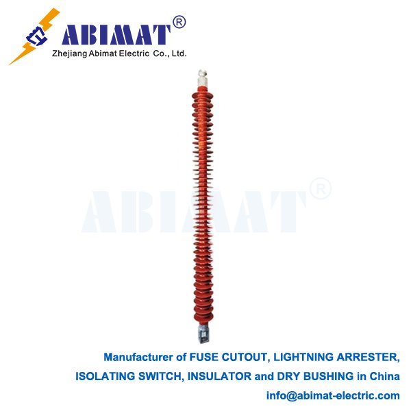
    Composite tension insulators—often called composite strain insulators—are key in overhead transmission lines. Engineers fit them to strain towers, such as dead-end or angle structures, because they must handle high pulling forces.  

    They replace older porcelain or glass insulators. Made by combining a fiber-reinforced polymer (FRP) core, a silicone rubber cover, and metal end pieces, this design gives them strong mechanical strength and good electrical performance. It works especially well in tough environments.

    Structure and Materials

    The core rod uses epoxy-impregnated glass fiber-reinforced plastic (GFRP). Manufacturers pick this material for its high tensile strength—at least 1,000 MPa—and low density, around 2 g/cm³. It bears the main mechanical load.

    Weathersheds are made from high-temperature vulcanized silicone rubber (HTV SR). This material naturally repels water, a key feature stopping pollution-caused flashovers. It keeps water from forming a continuous conductive film on the surface, working better in dirty, coastal, icy, or foggy spots.

    End fittings are hot-dip galvanized steel. They connect the insulator to the tower and conductor. The insulator’s performance depends much on the tight seal between the core rod and these fittings. Extreme temperatures can make the two materials expand differently here, weakening their bond.

    Performance Advantages

    Composite insulators are strong for their weight—5 to 10 times more than steel. This puts much less strain on the towers holding them. They pass tough fatigue tests, too: bending 200,000 times at 27 Hz, or handling wind shakes, shows they last long without wearing out.

    Electrically, they work better than many. The silicone rubber cover shares its water-repelling trait with dirt on the surface. This often doubles their pollution flashover voltage compared to similar porcelain insulators. In really dirty areas, you almost never need to clean them.

    They stand up to different environments, working reliably from −40°C to +40°C. But their pulling strength can drop at these extremes. The issue? End fittings and core rod expand differently with heat or cold. Staying in high temperatures a long time alone can cut their bond strength by over half.

    Design Considerations for Tension Applications

    Ultra-high voltage direct current (UHVDC) projects—think ±800 kV systems—often need composite tension insulators rated over 300 kN for V-string setups. Engineers use finite element analysis to check dynamic stresses: ice falling off, conductors galloping, or wind sway. These events can make static loads 1.5 to 2.5 times stronger, so designs need good safety factors.

    Installers must ensure end fittings rotate freely. This cuts bending or twisting stress during setup and use. Using two insulators side by side (parallel strings) boosts reliability; it also spreads torque better in tough strain uses.

    Good designs include thermal disconnectors, which isolate worn core parts. International standards—IEC 61109, GB/T 19519—set strict tests, making sure the design lasts over 30 years.

    Standards and Applications

    Composite tension insulators mainly follow IEC 61109 and GB/T 19519. Manufacturers make them for 35 kV to 500 kV systems, both AC and DC. They’ve been used successfully—like in Germany’s 245 kV network, running since 1967, and China’s big 500 kV setups. Field studies always find failure rates under 0.5%.

    Future Outlook

    Scientists are developing new silicone rubber, with nano-fillers to better resist electrical tracking and erosion. They’re also changing FRP core materials to stop hydrolysis. These improvements aim to let the insulators work in ultra-high-voltage (UHV) systems and grids in the harshest climates.

    Summary

    Composite tension insulators have great mechanical strength and handle pollution well. Light and low-maintenance, they help build more efficient power networks. Now widely used in key strain applications—spots once dominated by porcelain—they’ve proven reliable worldwide for decades. Material science keeps making them better, too.